


Exporting to a PC
• PC with SST installed
• Network connection cable
When exporting debug logs to a PC, a PC with SST installed and a network connection cable are required.
Common (When Exporting to a USB Device, or When Exporting to a PC)
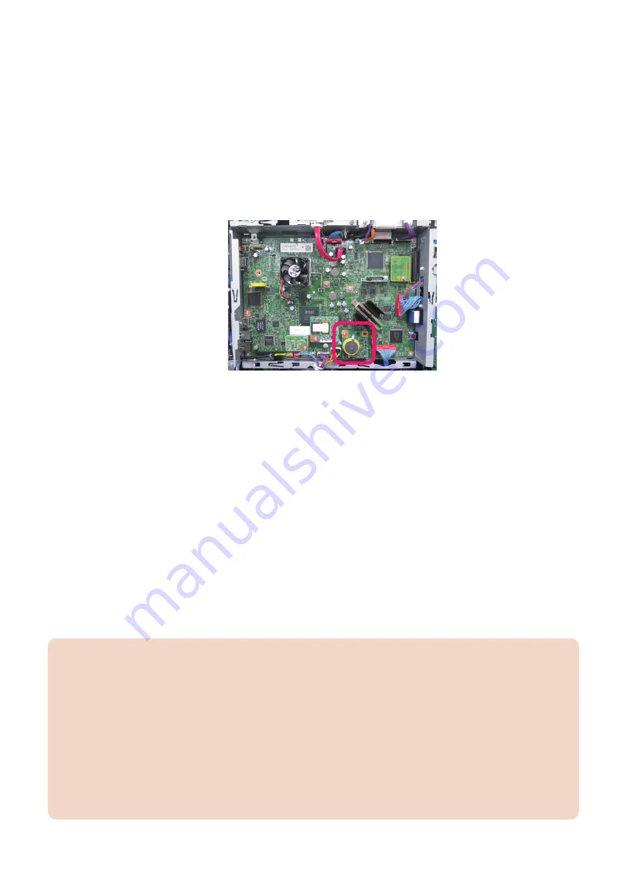
• DEBUG SRAM PCB ASS'Y Board
In the following conditions, debug logs cannot be saved, therefore the DEBUG SRAM PCB ASS'Y Board is required
when exporting debug logs to a USB Device or a PC.
• When restart is repeated
• When all the operations of the device are frozen and manual logs cannot be collected.
• When the machine would not recover from sleep mode
Refer to the following regarding installation on to the Controller PCB.
Reference example of installation
■ Work Flow
The flow of saving/collecting Sublogs is shown below.
1. Preparation
Refer to
“Flow of Determining the Procedure for Collecting Logs” on page 434
, and make the preparation as needed according
to a situation where an event has occurred.
2. Reproduction of the symptom
Reproduce the symptom.
3. Saving of manual logs
Save manual logs that require manual operation.
4. Output of reports
Output reports necessary for escalation.
5. Collecting log files
Start the machine in download mode, and save (collect) the log files to a USB device or a PC.
CAUTION:
In the case of analysis using Sublog, the following information needs to be obtained together with the Sublog.
• Symptom that has occurred (from service technician's viewpoint as far as possible)
• Date and time of the event (from an hour before the event to an hour after the event)
• Reports (P-Print, HIST-PRT, job logs, communication management report, etc.)
• Printed data and original at the time of reproduction (depends on the trouble that has occurred)
Besides Sublog, the above-mentioned information is required due to the following reasons:
• Failures such as a process being stopped due to an error or an unintended behavior are easy to find, but failures such
as "the behavior is slow" are difficult to analyze based on operation logs only.
• Since the number and size of the files are huge, the information helps to find the operation log where the problem
occurred.
• When R&D reproduces the failure, it is necessary to use information such as the procedure used by the customer,
frequency of use, and job data at the time of occurrence of the failure.
6. Troubleshooting
436
Содержание imageRUNNER ADVANCE C3330 Series
Страница 1: ...Revision 7 0 imageRUNNER ADVANCE C3330 C3325 C3320 Series Service Manual ...
Страница 18: ...Product Overview 1 Product Lineup 7 Features 11 Specifications 17 Parts Name 26 ...
Страница 278: ...J1335 J1066 J1022 J1146 J1050 J1051 J130 J1052 J1053 J1333 J120 J128 J130 4 Parts Replacement and Cleaning 266 ...
Страница 326: ...CAUTION Check that the color of the seal at the center is black 4 Parts Replacement and Cleaning 314 ...
Страница 359: ...6 Remove the Bottle Drive Unit 1 2 Bosses 2 5 Hooks 3 2 2 3 3 3 2 2 1 3 3 3 3 4 Parts Replacement and Cleaning 347 ...
Страница 399: ...Adjustment 5 Pickup Feed System 388 Document Exposure System 391 Actions after Replacement 393 ...
Страница 518: ...Error Jam Alarm 7 Overview 507 Error Code 511 Jam Code 617 Alarm Code 624 ...
Страница 1020: ...9 Installation 1008 ...
Страница 1022: ...2 Perform steps 3 to 5 in each cassette 9 Installation 1010 ...
Страница 1024: ...5 6 Checking the Contents Cassette Feeding Unit 1x 3x 2x 1x 9 Installation 1012 ...
Страница 1027: ...3 4 NOTE The removed cover will be used in step 6 5 2x 2x 9 Installation 1015 ...
Страница 1046: ...When the Kit Is Not Used 1 2 Close the Cassette 2 When the Kit Is Used 1 9 Installation 1034 ...
Страница 1058: ...3 4 CAUTION Be sure that the Inner 2 way Tray Support Member is installed properly 9 Installation 1046 ...
Страница 1062: ...Installation procedure 1 NOTE The work is the same when the Utility Tray is installed 9 Installation 1050 ...
Страница 1068: ... Removing the Covers 1 2x 2 1x 9 Installation 1056 ...
Страница 1070: ...3 1x 1x 9 Installation 1058 ...
Страница 1080: ...Installation Outline Drawing Installation Procedure 1 Remove the all tapes from this equipment 2 2x 9 Installation 1068 ...
Страница 1081: ...3 CAUTION To avoid damage do not pull the A part of the Utility Tray too much A 4 9 Installation 1069 ...
Страница 1083: ...6 7 TP M4x8 2x 2x 9 Installation 1071 ...
Страница 1084: ...When Installing the USB Keyboard 1 Cap Cover Wire Saddle 9 Installation 1072 ...
Страница 1095: ...9 2x 10 2x 11 Remove the Face Seals from the Reader Right Cover The removed Face Seals will not be used 9 Installation 1083 ...
Страница 1101: ... When Stopping to Use 1 Press Reset key or the Voice Recognition button for more than 3 seconds 9 Installation 1089 ...
Страница 1129: ...9 2x 10 2x 11 9 Installation 1117 ...
Страница 1135: ...Remove the covers 1 ws 2x 2 1x 9 Installation 1123 ...
Страница 1140: ...2 2x 3 Connect the power plug to the outlet 4 Turn ON the power switch 9 Installation 1128 ...
Страница 1155: ...Installation Outline Drawing Installation Procedure Removing the Covers 1 2x 2 1x 9 Installation 1143 ...
Страница 1157: ...3 Connect Power Cable and Signal Cable disconnected in the step 2 to the Encryption Board 2 Connectors 2x 9 Installation 1145 ...
Страница 1167: ...Installation Procedure Removing the Covers 1 2x 2 1x 3 2x Installing the Removable HDD Kit 9 Installation 1155 ...
Страница 1176: ... A 2x Installing the Covers 1 1x 2 2x 9 Installation 1164 ...
Страница 1177: ...3 4 2x Installing the Removable HDD 1 Install the HDD Unit to the HDD Slot 9 Installation 1165 ...
Страница 1182: ...Installation Outline Drawing Installation Procedure Removing the Covers 1 2x 2 1x 9 Installation 1170 ...
Страница 1190: ...14 Install the Cable Guide to the HDD Frame 4 Hooks 1 Boss 9 Installation 1178 ...
Страница 1195: ...23 Secure the Power Cable in place using the Wire Saddle 1x Installing the Covers 1 1x 2 2x 9 Installation 1183 ...
Страница 1196: ...3 4 2x Installing the Removable HDD 1 Install the HDD Unit to the HDD Slot 9 Installation 1184 ...


