


• Setting of the image ratio for executing the C-color toner ejection (Lv.2):
COPIER > OPTION > IMG-DEV > DELV-THC
• Setting of the image ratio for executing the Bk-color toner ejection (Lv.2):
COPIER > OPTION > IMG-DEV > DELV-THK
• ON/OFF of soiled paper edge prevention (Lv.2):
COPIER > OPTION > IMG-DEV > DELV-DNS
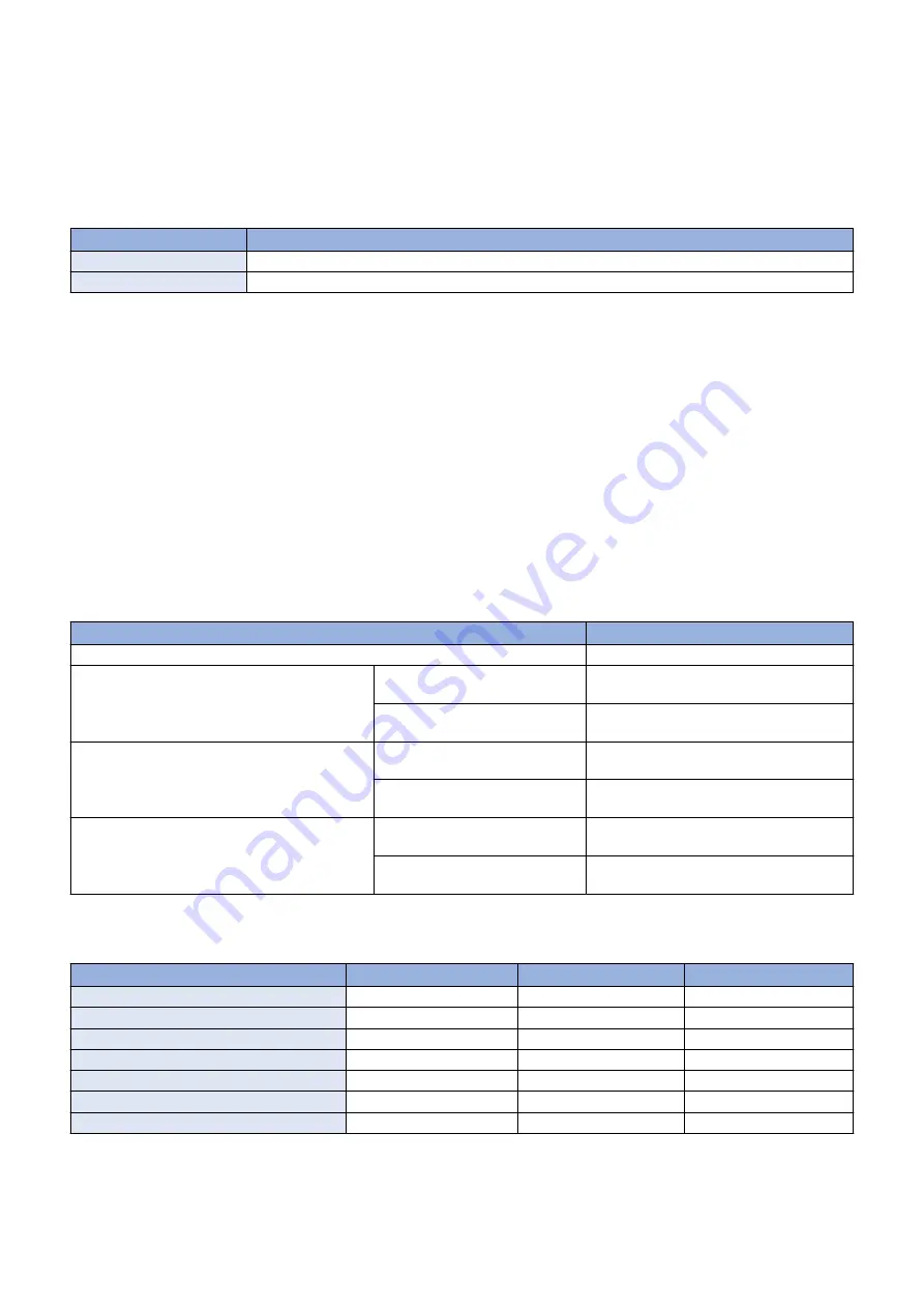
Transparency Black Band Sequence
Control timing
Condition
At paper intervals
For every 10 sheets of transparency
At job completion
For every 5 sheets of transparency
Since surfactant adheres to the ITB if a large volume of transparency film is fed, image failure due to degradation of transfer
efficiency occurs.
A 80 mm-wide solid Bk patch is formed on the ITB to remove the surfactant together with toner.
Related service mode
• Setting of the number of transparency to execute ITB cleaning (Lv.2):
COPIER > OPTION > CLEANING > OHP-PTH
● Warm-up Rotation Control
* The Developing Unit idle rotation time: Short: Approx. 15 seconds, Long: Approx. 30 seconds
Purpose
To check the status of sensor/motor at power-on or recovery from sleep mode.
Control description
According to the conditions, one of the following 3 patterns of warm-up rotation is performed: none, short, or long.
Condition
Pattern
Power-on
Short
When the power is turned ON (at quick startup)
(High temperature and high humid-
ity environment
None
Not a high temperature and high hu-
midity environment
None
When recovering from sleep mode (8 hours or more
have elapsed in sleep mode)
(High temperature and high humid-
ity environment
Long
Not a high temperature and high hu-
midity environment
Short
When the door is closed
(High temperature and high humid-
ity environment
None
Not a high temperature and high hu-
midity environment
None
Warm-up rotation control is not executed when "Insert the waste toner container.", "Replace the waste toner container.", or
"Replace toner cartridge. (Black)" is displayed.
Warm-up rotation control
Long
Short
None
Primary Transfer ATVC
Yes
Yes
No
Developing Unit idle rotation
Yes
Yes
No
Secondary Transfer Outer Roller cleaning
Yes
Yes
No
Patch Sensor adjustment
Yes
No
No
Laser light intensity correction (D-max) control
Yes
No
No
D-half control
Yes
No
No
ARCDAT
Yes
Yes
No
2. Technology
95
Содержание imageRUNNER ADVANCE C3330 Series
Страница 1: ...Revision 7 0 imageRUNNER ADVANCE C3330 C3325 C3320 Series Service Manual ...
Страница 18: ...Product Overview 1 Product Lineup 7 Features 11 Specifications 17 Parts Name 26 ...
Страница 278: ...J1335 J1066 J1022 J1146 J1050 J1051 J130 J1052 J1053 J1333 J120 J128 J130 4 Parts Replacement and Cleaning 266 ...
Страница 326: ...CAUTION Check that the color of the seal at the center is black 4 Parts Replacement and Cleaning 314 ...
Страница 359: ...6 Remove the Bottle Drive Unit 1 2 Bosses 2 5 Hooks 3 2 2 3 3 3 2 2 1 3 3 3 3 4 Parts Replacement and Cleaning 347 ...
Страница 399: ...Adjustment 5 Pickup Feed System 388 Document Exposure System 391 Actions after Replacement 393 ...
Страница 518: ...Error Jam Alarm 7 Overview 507 Error Code 511 Jam Code 617 Alarm Code 624 ...
Страница 1020: ...9 Installation 1008 ...
Страница 1022: ...2 Perform steps 3 to 5 in each cassette 9 Installation 1010 ...
Страница 1024: ...5 6 Checking the Contents Cassette Feeding Unit 1x 3x 2x 1x 9 Installation 1012 ...
Страница 1027: ...3 4 NOTE The removed cover will be used in step 6 5 2x 2x 9 Installation 1015 ...
Страница 1046: ...When the Kit Is Not Used 1 2 Close the Cassette 2 When the Kit Is Used 1 9 Installation 1034 ...
Страница 1058: ...3 4 CAUTION Be sure that the Inner 2 way Tray Support Member is installed properly 9 Installation 1046 ...
Страница 1062: ...Installation procedure 1 NOTE The work is the same when the Utility Tray is installed 9 Installation 1050 ...
Страница 1068: ... Removing the Covers 1 2x 2 1x 9 Installation 1056 ...
Страница 1070: ...3 1x 1x 9 Installation 1058 ...
Страница 1080: ...Installation Outline Drawing Installation Procedure 1 Remove the all tapes from this equipment 2 2x 9 Installation 1068 ...
Страница 1081: ...3 CAUTION To avoid damage do not pull the A part of the Utility Tray too much A 4 9 Installation 1069 ...
Страница 1083: ...6 7 TP M4x8 2x 2x 9 Installation 1071 ...
Страница 1084: ...When Installing the USB Keyboard 1 Cap Cover Wire Saddle 9 Installation 1072 ...
Страница 1095: ...9 2x 10 2x 11 Remove the Face Seals from the Reader Right Cover The removed Face Seals will not be used 9 Installation 1083 ...
Страница 1101: ... When Stopping to Use 1 Press Reset key or the Voice Recognition button for more than 3 seconds 9 Installation 1089 ...
Страница 1129: ...9 2x 10 2x 11 9 Installation 1117 ...
Страница 1135: ...Remove the covers 1 ws 2x 2 1x 9 Installation 1123 ...
Страница 1140: ...2 2x 3 Connect the power plug to the outlet 4 Turn ON the power switch 9 Installation 1128 ...
Страница 1155: ...Installation Outline Drawing Installation Procedure Removing the Covers 1 2x 2 1x 9 Installation 1143 ...
Страница 1157: ...3 Connect Power Cable and Signal Cable disconnected in the step 2 to the Encryption Board 2 Connectors 2x 9 Installation 1145 ...
Страница 1167: ...Installation Procedure Removing the Covers 1 2x 2 1x 3 2x Installing the Removable HDD Kit 9 Installation 1155 ...
Страница 1176: ... A 2x Installing the Covers 1 1x 2 2x 9 Installation 1164 ...
Страница 1177: ...3 4 2x Installing the Removable HDD 1 Install the HDD Unit to the HDD Slot 9 Installation 1165 ...
Страница 1182: ...Installation Outline Drawing Installation Procedure Removing the Covers 1 2x 2 1x 9 Installation 1170 ...
Страница 1190: ...14 Install the Cable Guide to the HDD Frame 4 Hooks 1 Boss 9 Installation 1178 ...
Страница 1195: ...23 Secure the Power Cable in place using the Wire Saddle 1x Installing the Covers 1 1x 2 2x 9 Installation 1183 ...
Страница 1196: ...3 4 2x Installing the Removable HDD 1 Install the HDD Unit to the HDD Slot 9 Installation 1184 ...


