


Memory area
TPM Chip
Root Key
TPM Key
Public Key Pair for
SSL Communication
Data Storing Key
Password
Encryption Key
User Certificate
Since the TPM key is safely
stored using the root key in
the TPM chip, high security
is maintained.
All information is encrypted and stored by the
TPM key which was encrypted by root key.
User Certificate
Data Storing Key
Public Key Pair for
SSL Communication
Password
Encryption Key
TPM Chip
Memory area
As it is practically impossible to extract the TPM key from the chip, the machine's security information is well protected even when
the following cases occur:
• If the hard disk or the Main Controller PCB is removed and installed in another MFP (as the TPM PCB retains the model
information when the TPM setting is enabled)
• If the machine's system is intruded upon via the network
The setting is required in Settings/Registration mode.
Management Settings > Data Management > TPM Settings > On (default: Off)
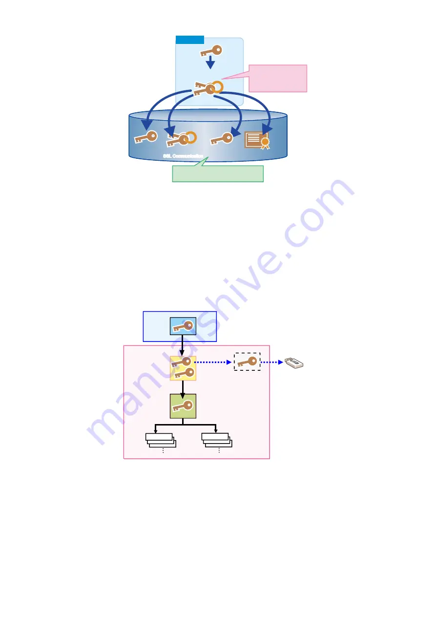
■ Security Information Structure
The operation of the security function differs depending on the TPM settings on the UI.
There are 2 types of TPM settings, and the respective flows of security information are described below:
Image diagram when the TPM settings are enabled
TPM PCB
TPM Key
Backup Key
for TPM failure
Public Key
Common
Key
Password
Flash PCB
USB flash drive
Password
When TPM settings are enabled, the TPM key becomes valid, so three-stage keys can be used. Therefore, the security information
of each machine is securely protected.
The security information for this setting consists of three keys and the information of multiple passwords stored in the Flash PCB.
Each piece of information is stored in the specified storage location. (enclosed in blue in the above diagram)
As this information is linked to the security information in the lower layer, the function does not work unless all information is
available.
Note that, as a backup function in the case of failure, a backup key is temporarily stored in the Flash memory. (Limited to the first
time when TPM Settings is turned to On)
This key can be backed up using a USB flash drive. After being backed up, it is deleted from the Flash PCB.
As the stored public key information is lost upon failure/replacement of the Flash PCB, the security information cannot be correctly
decoded. In this case, "Initialize All Data/Settings" of Settings/Registration needs to be executed to disable TPM settings.
When the TPM settings are disabled, the TPM key becomes invalid, so the security information is protected only by the shared
key. In that case, the security information of each machine is protected at the same level as that of conventional machines.
2. Technology
44
Содержание imageRUNNER ADVANCE C3330 Series
Страница 1: ...Revision 7 0 imageRUNNER ADVANCE C3330 C3325 C3320 Series Service Manual ...
Страница 18: ...Product Overview 1 Product Lineup 7 Features 11 Specifications 17 Parts Name 26 ...
Страница 278: ...J1335 J1066 J1022 J1146 J1050 J1051 J130 J1052 J1053 J1333 J120 J128 J130 4 Parts Replacement and Cleaning 266 ...
Страница 326: ...CAUTION Check that the color of the seal at the center is black 4 Parts Replacement and Cleaning 314 ...
Страница 359: ...6 Remove the Bottle Drive Unit 1 2 Bosses 2 5 Hooks 3 2 2 3 3 3 2 2 1 3 3 3 3 4 Parts Replacement and Cleaning 347 ...
Страница 399: ...Adjustment 5 Pickup Feed System 388 Document Exposure System 391 Actions after Replacement 393 ...
Страница 518: ...Error Jam Alarm 7 Overview 507 Error Code 511 Jam Code 617 Alarm Code 624 ...
Страница 1020: ...9 Installation 1008 ...
Страница 1022: ...2 Perform steps 3 to 5 in each cassette 9 Installation 1010 ...
Страница 1024: ...5 6 Checking the Contents Cassette Feeding Unit 1x 3x 2x 1x 9 Installation 1012 ...
Страница 1027: ...3 4 NOTE The removed cover will be used in step 6 5 2x 2x 9 Installation 1015 ...
Страница 1046: ...When the Kit Is Not Used 1 2 Close the Cassette 2 When the Kit Is Used 1 9 Installation 1034 ...
Страница 1058: ...3 4 CAUTION Be sure that the Inner 2 way Tray Support Member is installed properly 9 Installation 1046 ...
Страница 1062: ...Installation procedure 1 NOTE The work is the same when the Utility Tray is installed 9 Installation 1050 ...
Страница 1068: ... Removing the Covers 1 2x 2 1x 9 Installation 1056 ...
Страница 1070: ...3 1x 1x 9 Installation 1058 ...
Страница 1080: ...Installation Outline Drawing Installation Procedure 1 Remove the all tapes from this equipment 2 2x 9 Installation 1068 ...
Страница 1081: ...3 CAUTION To avoid damage do not pull the A part of the Utility Tray too much A 4 9 Installation 1069 ...
Страница 1083: ...6 7 TP M4x8 2x 2x 9 Installation 1071 ...
Страница 1084: ...When Installing the USB Keyboard 1 Cap Cover Wire Saddle 9 Installation 1072 ...
Страница 1095: ...9 2x 10 2x 11 Remove the Face Seals from the Reader Right Cover The removed Face Seals will not be used 9 Installation 1083 ...
Страница 1101: ... When Stopping to Use 1 Press Reset key or the Voice Recognition button for more than 3 seconds 9 Installation 1089 ...
Страница 1129: ...9 2x 10 2x 11 9 Installation 1117 ...
Страница 1135: ...Remove the covers 1 ws 2x 2 1x 9 Installation 1123 ...
Страница 1140: ...2 2x 3 Connect the power plug to the outlet 4 Turn ON the power switch 9 Installation 1128 ...
Страница 1155: ...Installation Outline Drawing Installation Procedure Removing the Covers 1 2x 2 1x 9 Installation 1143 ...
Страница 1157: ...3 Connect Power Cable and Signal Cable disconnected in the step 2 to the Encryption Board 2 Connectors 2x 9 Installation 1145 ...
Страница 1167: ...Installation Procedure Removing the Covers 1 2x 2 1x 3 2x Installing the Removable HDD Kit 9 Installation 1155 ...
Страница 1176: ... A 2x Installing the Covers 1 1x 2 2x 9 Installation 1164 ...
Страница 1177: ...3 4 2x Installing the Removable HDD 1 Install the HDD Unit to the HDD Slot 9 Installation 1165 ...
Страница 1182: ...Installation Outline Drawing Installation Procedure Removing the Covers 1 2x 2 1x 9 Installation 1170 ...
Страница 1190: ...14 Install the Cable Guide to the HDD Frame 4 Hooks 1 Boss 9 Installation 1178 ...
Страница 1195: ...23 Secure the Power Cable in place using the Wire Saddle 1x Installing the Covers 1 1x 2 2x 9 Installation 1183 ...
Страница 1196: ...3 4 2x Installing the Removable HDD 1 Install the HDD Unit to the HDD Slot 9 Installation 1184 ...


