


Embedded RDS
Product Overview
■ Overview
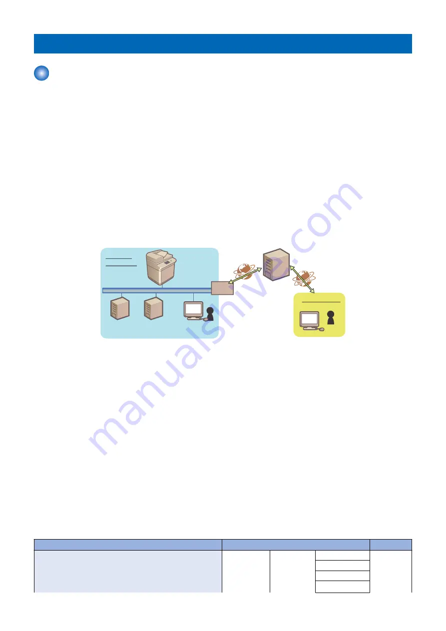
Embedded RDS (hereinafter referred to as E-RDS) is a monitoring program that runs on the host machine. When the monitoring
option is enabled by making the setting on this machine, information such as the status change of the machine, counter
information, and failure information are collected. The collected device information is sent to a remote maintenance server called
UGW (Universal Gateway Server) via Internet, thus allowing for e-Maintenance/ imageWARE Remote (Remote Diagnosis
System).
The following device information/ status can be monitored.
• Billing counts
• Parts counter
• Firmware info
• Service call error log
• Jam log
• Alarm log
• Status changes (Toner low/ out, etc.)
Since high confidentiality is required for the information shown above, it performs communication between this machine and the
UGW using HTTPS/ SOAP protocol.
㻲㼕㼞㼑㼣㼍㼘㼘
㼁㻳㼃
㻵㼚㼠㼑㼞㼚㼑㼠
㻰㻺㻿㻌㻿㼑㼞㼢㼑㼞
㼀㼔㼕㼟㻌㼙㼍㼏㼔㼕㼚㼑
㻼㼞㼛㼤㼥㻌㻿㼑㼞㼢㼑㼞
㻭㼐㼙㼕㼚㼕㼟㼠㼞㼍㼠㼛㼞
㻯㼡㼟㼠㼛㼙㼑㼞㻌
㻱㼚㼢㼕㼞㼛㼚㼙㼑㼚㼠
㻿㼍㼘㼑㼟㻌㻯㼛㼙㼜㼍㼚㼥
㻵㼚㼠㼑㼞㼚㼑㼠
■ Features and benefits
E-RDS embedded with a network module in advance can realize a front-end processing of e-Maintenance/ imageWARE Remote
system without attaching any extra hardware equipment.
■ Major Functions
● Service Browser
Service browser is a web browsing functionality only for service technicians in charge, and is used for referring to the FAQ contents
which is connected to UGW.
In order to grasp on which devices the service browser is enabled, when the status of the service browser is changed from disabled
(0: OFF) to enabled, E-RDS sends the browser information to the UGW.
● Service mode menu Transmission
E-RDS sends the target service mode menu data to UGW in the following cases:
• When a specific alarm and service call error are detected
• When the setting is changed in service mode
The following shows the transmission timing and the target data for transmission in service mode menu:
Transmission timing
Transmitting data
Error retry
When the following alarm is detected.
Alarm codes for transmission:
0x060002, // Fixing
0x060004 - 0x069999, // Fixing
0x090005 - 0x099999, // Dram
COPIER
Display
ANALOG
No
HV-STS
CCD
DPOT
2. Technology
185
Содержание imageRUNNER ADVANCE C3330 Series
Страница 1: ...Revision 7 0 imageRUNNER ADVANCE C3330 C3325 C3320 Series Service Manual ...
Страница 18: ...Product Overview 1 Product Lineup 7 Features 11 Specifications 17 Parts Name 26 ...
Страница 278: ...J1335 J1066 J1022 J1146 J1050 J1051 J130 J1052 J1053 J1333 J120 J128 J130 4 Parts Replacement and Cleaning 266 ...
Страница 326: ...CAUTION Check that the color of the seal at the center is black 4 Parts Replacement and Cleaning 314 ...
Страница 359: ...6 Remove the Bottle Drive Unit 1 2 Bosses 2 5 Hooks 3 2 2 3 3 3 2 2 1 3 3 3 3 4 Parts Replacement and Cleaning 347 ...
Страница 399: ...Adjustment 5 Pickup Feed System 388 Document Exposure System 391 Actions after Replacement 393 ...
Страница 518: ...Error Jam Alarm 7 Overview 507 Error Code 511 Jam Code 617 Alarm Code 624 ...
Страница 1020: ...9 Installation 1008 ...
Страница 1022: ...2 Perform steps 3 to 5 in each cassette 9 Installation 1010 ...
Страница 1024: ...5 6 Checking the Contents Cassette Feeding Unit 1x 3x 2x 1x 9 Installation 1012 ...
Страница 1027: ...3 4 NOTE The removed cover will be used in step 6 5 2x 2x 9 Installation 1015 ...
Страница 1046: ...When the Kit Is Not Used 1 2 Close the Cassette 2 When the Kit Is Used 1 9 Installation 1034 ...
Страница 1058: ...3 4 CAUTION Be sure that the Inner 2 way Tray Support Member is installed properly 9 Installation 1046 ...
Страница 1062: ...Installation procedure 1 NOTE The work is the same when the Utility Tray is installed 9 Installation 1050 ...
Страница 1068: ... Removing the Covers 1 2x 2 1x 9 Installation 1056 ...
Страница 1070: ...3 1x 1x 9 Installation 1058 ...
Страница 1080: ...Installation Outline Drawing Installation Procedure 1 Remove the all tapes from this equipment 2 2x 9 Installation 1068 ...
Страница 1081: ...3 CAUTION To avoid damage do not pull the A part of the Utility Tray too much A 4 9 Installation 1069 ...
Страница 1083: ...6 7 TP M4x8 2x 2x 9 Installation 1071 ...
Страница 1084: ...When Installing the USB Keyboard 1 Cap Cover Wire Saddle 9 Installation 1072 ...
Страница 1095: ...9 2x 10 2x 11 Remove the Face Seals from the Reader Right Cover The removed Face Seals will not be used 9 Installation 1083 ...
Страница 1101: ... When Stopping to Use 1 Press Reset key or the Voice Recognition button for more than 3 seconds 9 Installation 1089 ...
Страница 1129: ...9 2x 10 2x 11 9 Installation 1117 ...
Страница 1135: ...Remove the covers 1 ws 2x 2 1x 9 Installation 1123 ...
Страница 1140: ...2 2x 3 Connect the power plug to the outlet 4 Turn ON the power switch 9 Installation 1128 ...
Страница 1155: ...Installation Outline Drawing Installation Procedure Removing the Covers 1 2x 2 1x 9 Installation 1143 ...
Страница 1157: ...3 Connect Power Cable and Signal Cable disconnected in the step 2 to the Encryption Board 2 Connectors 2x 9 Installation 1145 ...
Страница 1167: ...Installation Procedure Removing the Covers 1 2x 2 1x 3 2x Installing the Removable HDD Kit 9 Installation 1155 ...
Страница 1176: ... A 2x Installing the Covers 1 1x 2 2x 9 Installation 1164 ...
Страница 1177: ...3 4 2x Installing the Removable HDD 1 Install the HDD Unit to the HDD Slot 9 Installation 1165 ...
Страница 1182: ...Installation Outline Drawing Installation Procedure Removing the Covers 1 2x 2 1x 9 Installation 1170 ...
Страница 1190: ...14 Install the Cable Guide to the HDD Frame 4 Hooks 1 Boss 9 Installation 1178 ...
Страница 1195: ...23 Secure the Power Cable in place using the Wire Saddle 1x Installing the Covers 1 1x 2 2x 9 Installation 1183 ...
Страница 1196: ...3 4 2x Installing the Removable HDD 1 Install the HDD Unit to the HDD Slot 9 Installation 1184 ...


