


Backup/Restore
Overview
■ Backup/Restore Overview
It may sometimes become necessary to back up and restore the data in the machine during maintenance.
Examples of when it is necessary to back up and restore data are indicated below.
• Replacing the hard disk
• Replacing the machine
At the time of replacing controller PCBs, the backup function enables to save data held in the PCB to migrate them to the new
PCB.
This section describes the procedure for backup and restoration using SST or a USB device.
NOTE:
Before replacing the DC controller PCBs, back up the data from Service mode. The backup data can be restored from Service
mode when the PCBs are replaced. This enables to maintain the setting data including Service mode stored in the old Controller
PCB.
Backup by main power OFF
The setting value that was set when the main power was turned OFF the last time is automatically backed up to the Flash PCB.
When a HDD is replaced with a new one, the setting value is automatically inherited from the Flash PCB at the time of HDD
formatting (
“Formatting the Hard Disk with SST” on page 502
“Formatting FLASH PCB or Hard Disk by Download Mode” on
).
Backup target data
Settings / Registration
Preferences (Except for Paper Type Management Settings)
Adjustment/Maintenance(*)
Function Settings (Except for Printer Custom Settings, Forwarding Settings)
Set Destination (Except for Address List)
Management Settings (Except for Address List)
Printer Settings
Box settings
Network Place Settings
Service Mode
Service Mode setting values (MN-CON)
When changing the settings of Settings/Registration or service mode, it is recommended to restart the device without fail in order
to keep the backup of the setting values saved in the Flash PCB up to date.
Checking the backup data
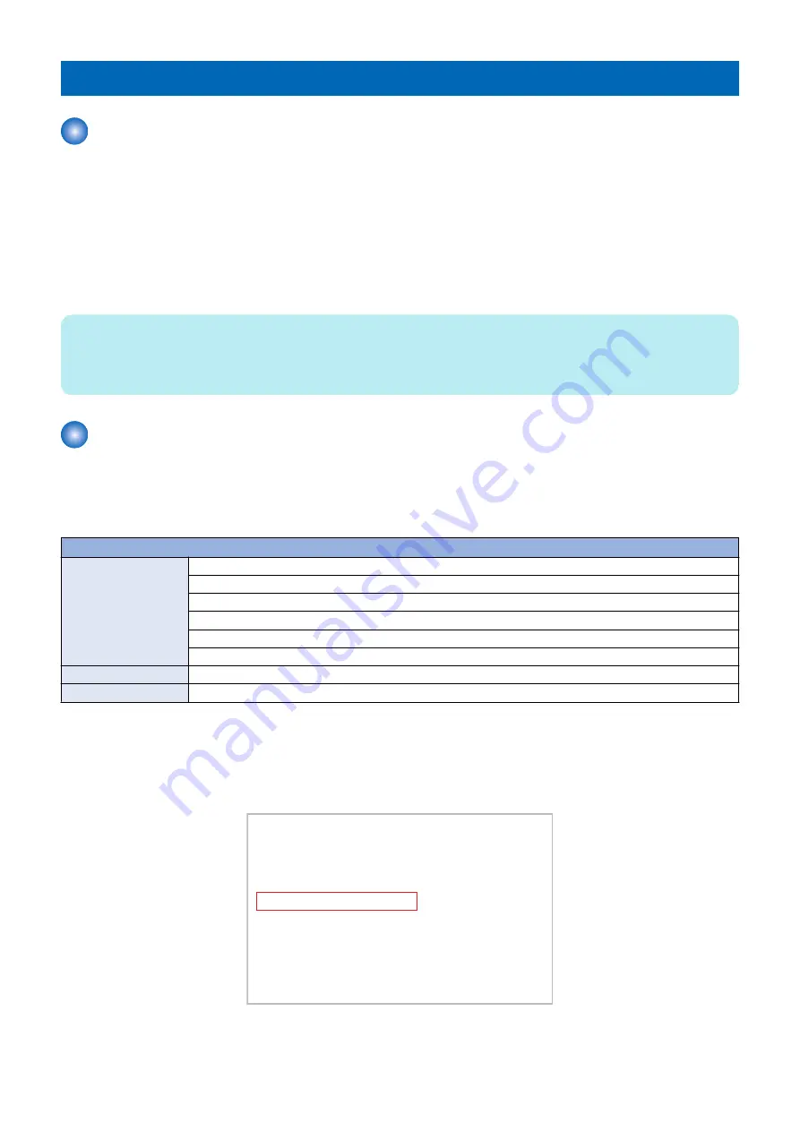
If data that has been backed up exists, the date when it was backed up can be checked in safe mode.
[ [ [ [ [ [ [ [ [ [ Backup/Restore Menu (USB) ] ] ] ] ] ] ] ] ]
-------------------------------------------------------------------------
[1] : SRAM Backup
[2] : SRAM Restore
[3] : MEAP Backup
[4] : MEAP Restore
[C] : Return to Menu
(Settings data backup date @ 2015/9/3
Do not turn OFF power without executing the shutdown sequence.
* The above-mentioned date is calculated based on the GMT standard time and displayed.
6. Troubleshooting
495
Содержание imageRUNNER ADVANCE C3330 Series
Страница 1: ...Revision 7 0 imageRUNNER ADVANCE C3330 C3325 C3320 Series Service Manual ...
Страница 18: ...Product Overview 1 Product Lineup 7 Features 11 Specifications 17 Parts Name 26 ...
Страница 278: ...J1335 J1066 J1022 J1146 J1050 J1051 J130 J1052 J1053 J1333 J120 J128 J130 4 Parts Replacement and Cleaning 266 ...
Страница 326: ...CAUTION Check that the color of the seal at the center is black 4 Parts Replacement and Cleaning 314 ...
Страница 359: ...6 Remove the Bottle Drive Unit 1 2 Bosses 2 5 Hooks 3 2 2 3 3 3 2 2 1 3 3 3 3 4 Parts Replacement and Cleaning 347 ...
Страница 399: ...Adjustment 5 Pickup Feed System 388 Document Exposure System 391 Actions after Replacement 393 ...
Страница 518: ...Error Jam Alarm 7 Overview 507 Error Code 511 Jam Code 617 Alarm Code 624 ...
Страница 1020: ...9 Installation 1008 ...
Страница 1022: ...2 Perform steps 3 to 5 in each cassette 9 Installation 1010 ...
Страница 1024: ...5 6 Checking the Contents Cassette Feeding Unit 1x 3x 2x 1x 9 Installation 1012 ...
Страница 1027: ...3 4 NOTE The removed cover will be used in step 6 5 2x 2x 9 Installation 1015 ...
Страница 1046: ...When the Kit Is Not Used 1 2 Close the Cassette 2 When the Kit Is Used 1 9 Installation 1034 ...
Страница 1058: ...3 4 CAUTION Be sure that the Inner 2 way Tray Support Member is installed properly 9 Installation 1046 ...
Страница 1062: ...Installation procedure 1 NOTE The work is the same when the Utility Tray is installed 9 Installation 1050 ...
Страница 1068: ... Removing the Covers 1 2x 2 1x 9 Installation 1056 ...
Страница 1070: ...3 1x 1x 9 Installation 1058 ...
Страница 1080: ...Installation Outline Drawing Installation Procedure 1 Remove the all tapes from this equipment 2 2x 9 Installation 1068 ...
Страница 1081: ...3 CAUTION To avoid damage do not pull the A part of the Utility Tray too much A 4 9 Installation 1069 ...
Страница 1083: ...6 7 TP M4x8 2x 2x 9 Installation 1071 ...
Страница 1084: ...When Installing the USB Keyboard 1 Cap Cover Wire Saddle 9 Installation 1072 ...
Страница 1095: ...9 2x 10 2x 11 Remove the Face Seals from the Reader Right Cover The removed Face Seals will not be used 9 Installation 1083 ...
Страница 1101: ... When Stopping to Use 1 Press Reset key or the Voice Recognition button for more than 3 seconds 9 Installation 1089 ...
Страница 1129: ...9 2x 10 2x 11 9 Installation 1117 ...
Страница 1135: ...Remove the covers 1 ws 2x 2 1x 9 Installation 1123 ...
Страница 1140: ...2 2x 3 Connect the power plug to the outlet 4 Turn ON the power switch 9 Installation 1128 ...
Страница 1155: ...Installation Outline Drawing Installation Procedure Removing the Covers 1 2x 2 1x 9 Installation 1143 ...
Страница 1157: ...3 Connect Power Cable and Signal Cable disconnected in the step 2 to the Encryption Board 2 Connectors 2x 9 Installation 1145 ...
Страница 1167: ...Installation Procedure Removing the Covers 1 2x 2 1x 3 2x Installing the Removable HDD Kit 9 Installation 1155 ...
Страница 1176: ... A 2x Installing the Covers 1 1x 2 2x 9 Installation 1164 ...
Страница 1177: ...3 4 2x Installing the Removable HDD 1 Install the HDD Unit to the HDD Slot 9 Installation 1165 ...
Страница 1182: ...Installation Outline Drawing Installation Procedure Removing the Covers 1 2x 2 1x 9 Installation 1170 ...
Страница 1190: ...14 Install the Cable Guide to the HDD Frame 4 Hooks 1 Boss 9 Installation 1178 ...
Страница 1195: ...23 Secure the Power Cable in place using the Wire Saddle 1x Installing the Covers 1 1x 2 2x 9 Installation 1183 ...
Страница 1196: ...3 4 2x Installing the Removable HDD 1 Install the HDD Unit to the HDD Slot 9 Installation 1184 ...


