
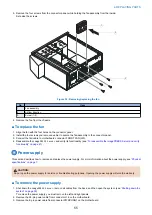


4. Remove the SATA power cables from the hard disk drives.
5. Detach the SATA power cable from the power connector of the dual cable for the DVD drive.
6. Detach the 8-pin power cable from the connector from the Fiery QuickTouch.
7. Remove any tie-wraps securing the power cables to the chassis.
8. Place the
imagePRESS Server
in the upright position.
9. Remove the motherboard from the chassis (see
“To replace boards, cables, and components” on page 46
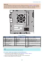
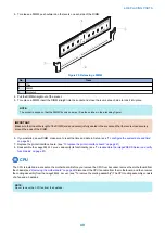
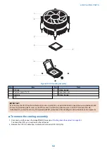
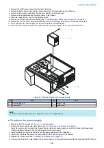
10. Remove the four connector panel screws that secure the power supply to the back of the chassis (see below).
11. While squeezing the power supply unit, remove the inside screw with washer.
12. Slide the power supply toward the front panel and take the power supply off from under the chassis bar.
1
3
4
2
Figure 33: Removing/replacing the power supply
No.
Item
No.
Item
1
Power supply unit
3
Screw (1 of 4)
2
Chassis bar
4
Inside screw
NOTE:
To service the power supply, place the
imagePRESS Server
in an upright position.
■ To replace the power supply
1. Make sure that the
imagePRESS Server
is in upright position.
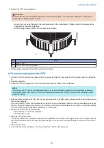
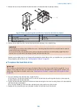
2. Position the power supply inside the chassis (see
“To remove the power supply” on page 55
Insert the power supply unit under the chassis bar, and place the power supply on top of the left and right chassis bars.
Position the power supply so that it is flush against the connector panel.
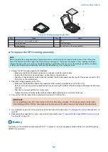
3. Install the inside screw with washer to secure the power supply unit to the chassis top.
4. Install the four screws that secure the power supply to the connector panel of the chassis.
5. Replace the motherboard (see
“To replace the motherboard” on page 45
)
6. Connect one of the SATA power cables to the power connector on the dual data/power cable that connects to the DVD drive.
4. REPLACING PARTS
56
Содержание ImagePRESS Server H350 V2
Страница 8: ...Introduction 1 Introduction 2 Specifications 7 ...
Страница 17: ...INSTALLING HARDWARE 2 Installing Hardware 11 ...
Страница 26: ...USING THE IMAGEPRESS SERVER 3 Using the imagePRESS Server 20 ...
Страница 35: ...REPLACING PARTS 4 Replacing parts 29 ...
Страница 38: ...1 2 Figure 19 Inside the front panel No Item 1 DVD drive 2 DVD eject button 4 REPLACING PARTS 31 ...
Страница 86: ...INSTALLING SYSTEM SOFTWARE 6 Installing System Software 80 ...
Страница 91: ...TROUBLESHOOTI NG 7 Troubleshooting 85 ...
Страница 104: ...INSTALLATION PROCEDURE 8 Installation 98 Removable HDD Kit B5 108 ...