16
4
11
7
14
15
13
6
3
5
8
10
12
9
17
18
2
1
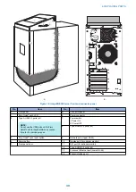
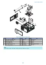
Figure 20: Exploded view of components
No.
Item
No.
Item
No.
Item
1
Fiery QuickTouch USB3.0 cable
7
DIMM (x2)
13
Hard disk drive
2
Hard disk drive data cables
8
CPU
14
DVD drive
3
DVD drive data cable
9
Battery
15
Chassis
4
Printer interface board
10
Motherboard
16
Rear fan
5
Fiery QuickTouch power cable
11
Front panel
17
Fiery QuickTouch display
6
CPU cooling assembly
12
Power supply
18
Top panel
NOTE:
CPU fan cable, tie-wraps, cable clamps, dongle(s), and external cables are not shown.
4. REPLACING PARTS
32
Содержание ImagePRESS Server H350 V2
Страница 8: ...Introduction 1 Introduction 2 Specifications 7 ...
Страница 17: ...INSTALLING HARDWARE 2 Installing Hardware 11 ...
Страница 26: ...USING THE IMAGEPRESS SERVER 3 Using the imagePRESS Server 20 ...
Страница 35: ...REPLACING PARTS 4 Replacing parts 29 ...
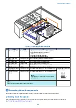
Страница 38: ...1 2 Figure 19 Inside the front panel No Item 1 DVD drive 2 DVD eject button 4 REPLACING PARTS 31 ...
Страница 86: ...INSTALLING SYSTEM SOFTWARE 6 Installing System Software 80 ...
Страница 91: ...TROUBLESHOOTI NG 7 Troubleshooting 85 ...
Страница 104: ...INSTALLATION PROCEDURE 8 Installation 98 Removable HDD Kit B5 108 ...

