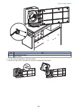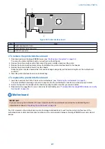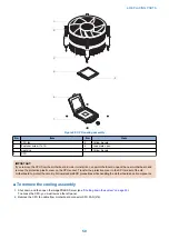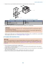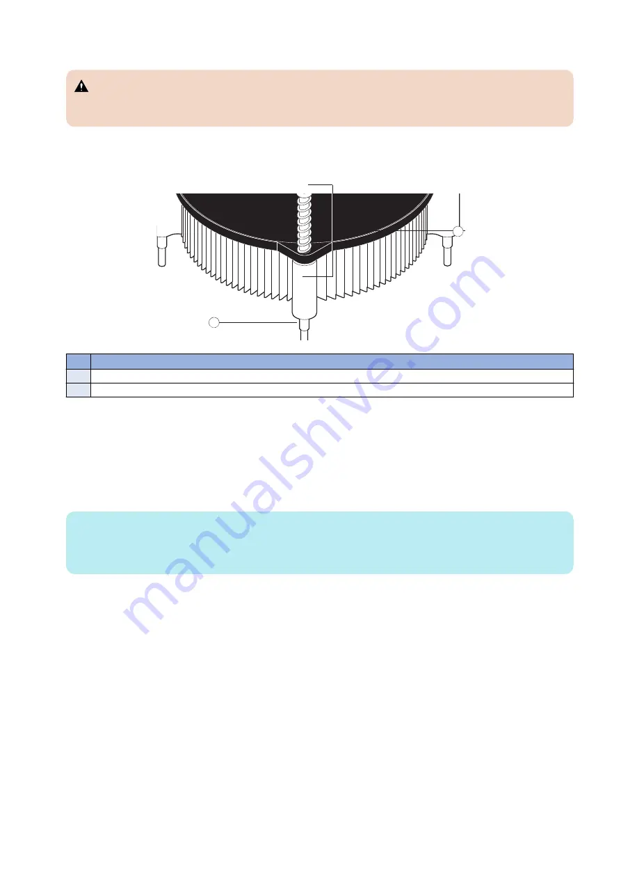
3. Remove the CPU cooling assembly.
CAUTION:
Be aware that both the cooling assembly and the CPU may be very hot. You may need to allow the components to
cool before you attempt to remove them.
• Loosen the four screws that secure the cooling assembly to the motherboard. Partially loosen all the screws before
loosening any one screw all the way.
• Lift the cooling assembly off the CPU socket and set it aside.
1
2
No.
Item
1
Screw (1 of 4)
2
Loosen each screw to this position.
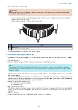
4. Lift the cooling assembly off the CPU socket and set it aside.
■ To remove and replace the CPU
1. Unlock the CPU socket lever and raise it into the open position (flex the lever away from the retention post, and then raise
it).
2. Open the load plate.
3. Grasp the CPU by its edges, lift it out of the socket, and then place the CPU in a safe place.
NOTE:
If you remove the CPU from the motherboard to install it on a new motherboard, unpack the new motherboard and remove
the protective plastic cover from the CPU socket. Transfer the protective cover to the CPU socket of the old motherboard to
protect the circuitry.
4. Wipe the contact surface of the CPU (the smooth, gray side of the chip) with a clean, lint-free cloth to ensure proper contact
with the new heatsink.
If you remove the CPU from the motherboard to install it on a new motherboard, make sure that you completely remove any
thermal compound residue on the surface of the CPU and at the base of the heatsink. It may help to scrape all the residue
off of the surface using the flat edge of something non-conductive.
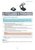
5. Prepare the CPU socket by ensuring that:
• The socket lever is in the open position.
• The load plate is open.
6. Place the CPU in the socket.
The CPU and the socket are keyed to ensure correct installation. The notches on the edges of the CPU correspond with the
two small posts inside the socket. Align the yellow triangle on the CPU with the yellow triangle on the socket. Do not force
the CPU.
7. Close the load plate.
8. Lower the socket lever and place it in the locked position under the retention post.
4. REPLACING PARTS
51
Содержание ImagePRESS Server H350 V2
Страница 8: ...Introduction 1 Introduction 2 Specifications 7 ...
Страница 17: ...INSTALLING HARDWARE 2 Installing Hardware 11 ...
Страница 26: ...USING THE IMAGEPRESS SERVER 3 Using the imagePRESS Server 20 ...
Страница 35: ...REPLACING PARTS 4 Replacing parts 29 ...
Страница 38: ...1 2 Figure 19 Inside the front panel No Item 1 DVD drive 2 DVD eject button 4 REPLACING PARTS 31 ...
Страница 86: ...INSTALLING SYSTEM SOFTWARE 6 Installing System Software 80 ...
Страница 91: ...TROUBLESHOOTI NG 7 Troubleshooting 85 ...
Страница 104: ...INSTALLATION PROCEDURE 8 Installation 98 Removable HDD Kit B5 108 ...

