Section 4. Quickstart Tutorial
40
4.1.3.3.3 Pulse Sensor Wiring
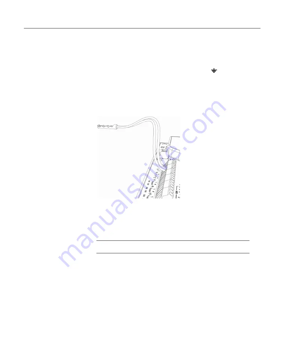
Wiring a pulse sensor to a CR800 is straight forward, as shown in figure
Pulse-
Input Wiring -- Anemometer Switch
(p. 40).
Pulse sensors have two active wires,
one of which is always ground. Connect the ground wire to a
(ground)
channel. Connect the other wire to a pulse channel. Sometimes the sensor will
require power from the CR800, so there will be two more wires – one of which is
always ground. Connect power ground to a
G
channel. Do not confuse the pulse
wire with the positive power wire, or damage to the sensor or CR800 may result.
Some switch-closure sensors may require a pull-up resistor. Consult figure
Connecting Switch Closures to Digital I/O
(p. 303)
for information on use of pull-up
resistors.
Figure 8: Pulse-input wiring -- anemometer switch
4.1.3.4 RS-232 Sensors
The CR800 has 4 ports available for RS-232 input as shown in figure
Location of
RS-232 Ports
(p. 41).
Note
With the correct adaptor, the
CS I/O
port can be used as an RS-232 I/O
port.
As indicated in figure
Use of RS-232 and Digital I/O when Reading RS-232
Devices
(p. 41),
RS-232 sensors can be connected to the
RS-232
port or to digital
I/O port pairs. Ports can be set up with various baud rates, parity options, stop-bit
options, and so forth as defined in
CRBasic Editor Help
.
Содержание CR850
Страница 2: ......
Страница 4: ......
Страница 6: ......
Страница 26: ...Table of Contents 26...
Страница 30: ...Section 2 Cautionary Statements 30...
Страница 32: ...Section 3 Initial Inspection 32...
Страница 35: ...Section 4 Quickstart Tutorial 35 Figure 2 Wiring panel...
Страница 55: ...Section 4 Quickstart Tutorial 55 Figure 24 PC200W View data utility...
Страница 78: ...Section 5 System Overview 78...
Страница 80: ...Section 6 CR800 Specifications 80...
Страница 95: ...Section 7 Installation 95 Figure 35 DevConfig OS download window Figure 36 Dialog box confirming OS download...
Страница 104: ...Section 7 Installation 104 Figure 43 Include File settings via DevConfig Figure 44 Include File settings via PakBusGraph...
Страница 267: ...Section 7 Installation 267 Figure 84 Running average signal attenuation...
Страница 268: ...Section 7 Installation 268...
Страница 384: ...Section 8 Operation 384 Figure 113 Using the keyboard display...
Страница 385: ...Section 8 Operation 385 8 8 1 Data Display Figure 114 Displaying data with the keyboard display...
Страница 387: ...Section 8 Operation 387 Figure 116 Real time custom...
Страница 388: ...Section 8 Operation 388 8 8 1 3 Final Storage Tables Figure 117 Final storage tables...
Страница 389: ...Section 8 Operation 389 8 8 2 Run Stop Program Figure 118 Run Stop Program...
Страница 390: ...Section 8 Operation 390 8 8 3 File Display Figure 119 File display...
Страница 396: ...Section 8 Operation 396...
Страница 402: ...Section 9 Maintenance 402...
Страница 450: ...Section 11 Glossary 450...
Страница 504: ...Appendix A CRBasic Programming Instructions 504...
Страница 526: ...Appendix B Status Table and Settings 526...
Страница 530: ...Appendix C Serial Port Pinouts 530...
Страница 536: ...Appendix E FP2 Data Format 536...
Страница 550: ...Appendix F Other Campbell Scientific Products 550...
Страница 564: ...Index 564 WriteIO 464 Writing Program 108 X XML 448 XOR 473 Y Y intercept 141 142 Z Zero 155 166 Zero Basis 151...
Страница 565: ......


