Section 7. Installation
174
•
Programmed mode automates much of the SDI-12 protocol and provides for
data recording.
7.8.3.1 SDI-12 Transparent Mode
System operators can manually interrogate and enter settings in probes using
transparent mode. Transparent mode is useful in troubleshooting SDI-12 systems
because it allows direct communication with probes.
Transparent mode may need to wait for commands issued by the programmed
mode to finish before sending responses. While in transparent mode, CR800
programs may not execute. CR800 security may need to be unlocked before
transparent mode can be activated.
Transparent mode is entered while the PC is in telecommunications with the
CR800 through a terminal emulator program. It is easily accessed through
Campbell Scientific
datalogger support software
(p. 76),
but may also be accessible
with terminal emulator programs such as Windows Hyperterminal. Keyboard
displays cannot be used.
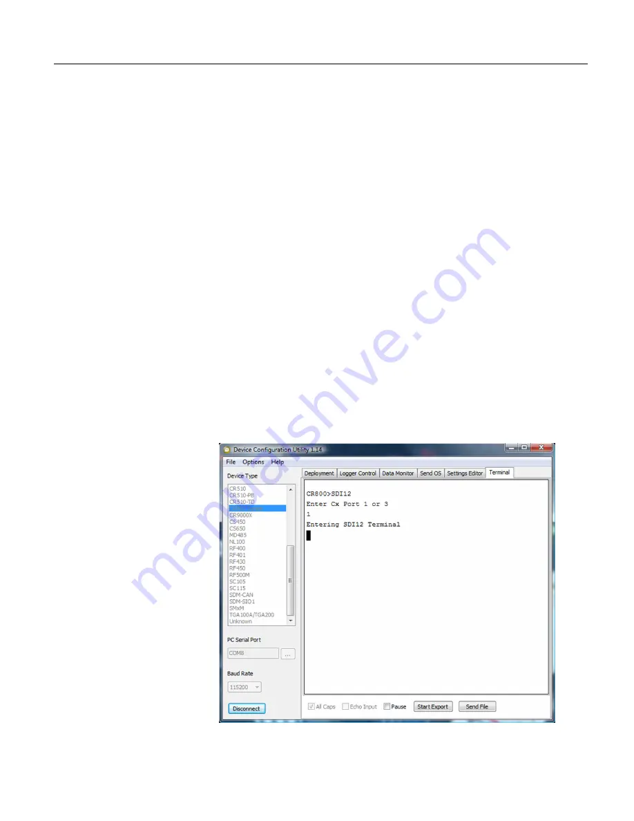
To enter the SDI-12 transparent mode, enter the datalogger support software
terminal emulator as shown in figure
Entering SDI-12 Transparent Mode
(p. 174).
Press
Enter
until the CR800 responds with the prompt
CR800>
. Type
SDI12
at
the prompt and press
Enter
. In response, the query
Enter Cx Port 1 or 3
will
appear. Enter the control port integer, that is
1
to
4,
to which the SDI-12 sensor is
connected. An
Entering SDI12 Terminal
response indicates that SDI-12
transparent mode is active and ready to transmit SDI-12 commands and display
responses.
Figure 57: Entering SDI-12 transparent mode
Содержание CR850
Страница 2: ......
Страница 4: ......
Страница 6: ......
Страница 26: ...Table of Contents 26...
Страница 30: ...Section 2 Cautionary Statements 30...
Страница 32: ...Section 3 Initial Inspection 32...
Страница 35: ...Section 4 Quickstart Tutorial 35 Figure 2 Wiring panel...
Страница 55: ...Section 4 Quickstart Tutorial 55 Figure 24 PC200W View data utility...
Страница 78: ...Section 5 System Overview 78...
Страница 80: ...Section 6 CR800 Specifications 80...
Страница 95: ...Section 7 Installation 95 Figure 35 DevConfig OS download window Figure 36 Dialog box confirming OS download...
Страница 104: ...Section 7 Installation 104 Figure 43 Include File settings via DevConfig Figure 44 Include File settings via PakBusGraph...
Страница 267: ...Section 7 Installation 267 Figure 84 Running average signal attenuation...
Страница 268: ...Section 7 Installation 268...
Страница 384: ...Section 8 Operation 384 Figure 113 Using the keyboard display...
Страница 385: ...Section 8 Operation 385 8 8 1 Data Display Figure 114 Displaying data with the keyboard display...
Страница 387: ...Section 8 Operation 387 Figure 116 Real time custom...
Страница 388: ...Section 8 Operation 388 8 8 1 3 Final Storage Tables Figure 117 Final storage tables...
Страница 389: ...Section 8 Operation 389 8 8 2 Run Stop Program Figure 118 Run Stop Program...
Страница 390: ...Section 8 Operation 390 8 8 3 File Display Figure 119 File display...
Страница 396: ...Section 8 Operation 396...
Страница 402: ...Section 9 Maintenance 402...
Страница 450: ...Section 11 Glossary 450...
Страница 504: ...Appendix A CRBasic Programming Instructions 504...
Страница 526: ...Appendix B Status Table and Settings 526...
Страница 530: ...Appendix C Serial Port Pinouts 530...
Страница 536: ...Appendix E FP2 Data Format 536...
Страница 550: ...Appendix F Other Campbell Scientific Products 550...
Страница 564: ...Index 564 WriteIO 464 Writing Program 108 X XML 448 XOR 473 Y Y intercept 141 142 Z Zero 155 166 Zero Basis 151...
Страница 565: ......


