Calsense 500 Series Скачать руководство пользователя страница 53


 ®                                                                   

SECTION 11 (-FL) FLOWSENSE

®


making

         since 1986


water work


SECTION 11:   (-FL) FLOWSENSE

®


The Calsense 

FLOWSENSE

®


option allows the user 

to manage an irrigation system that has one or more 
points of connection and one or more controllers 
sharing these points of connection. 

FLOWSENSE

® 

affords the user the following: 
 

  No more scheduling conflicts between 

multiple controllers 

  Eliminates relays when sharing pumps or 

master valves with several controllers 

  Manage the number of valves ON based 

upon flow capacities 

  Water management capabilities with or 

without a flow meter 

  Pump performance managed for electrical 

savings 


Setup in the field without a central computer 


Note:

 The above listed items are only feasible with 

two or more controllers in a communications chain.  


A. MULTIPLE CONTROLLER 

           COMMUNICATION SETUP 


Note: 

A chain is defined as a set of controllers 

connected together via the same communications 
type and / or frequency.  


Note:

 All of the controllers in the chain must be able 

to communicate with each other via (-SR) Spread 
Spectrum Radio, or (-M) Hardwired.  


From the MAIN MENU screen. 


1. 

          Press the 

SETUP

 Menu key.


2. 

          Press the 

COMMUNICATIONS


                         Menu key.


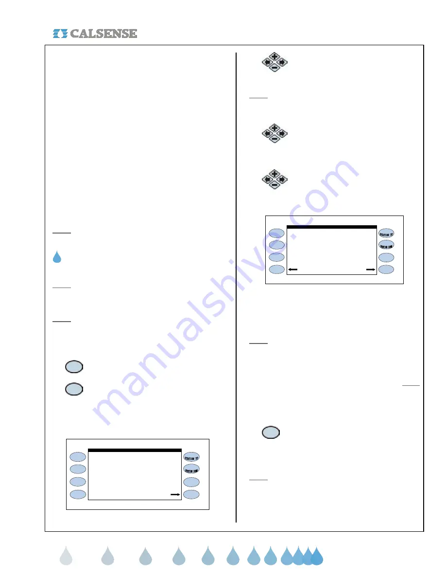
The COMMUNICATION ADDRESS screen  
(Figure 11.1). 
 

                                                   NO

                                                                       Controller Info


                          Communications  Address:  ! ! A

               other  controllers  to share MASTER
                   VALVES,  FLOW  METERS,  or  PUMPS?

ET2000-40-MSR-FL                                                                   (576.i)

             does    this    controller    coordinate   with

                       Using   FLOWSENSE  Technology


Figure 11.1 

3. 

      Press the 

PLUS

 or 

MINUS

 keys to   

                         change the NO to a YES setting. 
 

Note:

 Each controller in the communications chain 

must have the (-FL) option and will have to be set to 
YES. 


4. 

     Press the blue 

ARROW

 keys to  

                        move the cursor to the next question.   
                        NUMBER OF CONTROLLERS IN  
                        SYSTEM ?. 

5. 

     Press the 

PLUS

 or 

MINUS

 keys to  

                        change the amount of controllers in  
                        the system (Figure 11.2). 
 

                                                  YES

              other  controllers  to share MASTER
                  VALVES,  FLOW  METERS,  or  PUMPS?

ET2000-40-MSR-FL                                                                   (576.i)

            does    this    controller    coordinate   with

                      Using   FLOWSENSE  Technology

Number  of  controllers  in  system  ?    2


                         Communications  Address:  ! ! A

              Scan  Results                                 Controller Info


Figure 11.2 


Repeat the process described above until all three 
characters are set (The character furthest to the right 
must be a letter). 


Note:

 With multiple controllers one of the controllers 

must be the Master with an address ending in a 
Capitol “A”. All other controllers will have addresses 
ending in B, C, D, etc. No two controllers can have 
the same exact address when communicating to the 
same central computer. The Master controller 

must


be the controller communicating back to the central. 


If you desire to look at the controller’s 
communications information: 


6. 

         Press the 

CONTROLLER INFO


 Menu key to go to the PART &  

                        SERIAL NUMBERS screen  
                        (Figure 11.3). 


Note: 

This will allow you to look at the controller’s 

ROM version, Baud Rates, Part number, and 
Command center software version required to 
communicate with this controller. 

Содержание 500 Series

Страница 1: ...ET2000 500 SERIES PROGRAMMING GUIDE making since 1986 water work ET2000 500 SERIES IRRIGATION CONTROLLER PROGRAMMING GUIDE...

Страница 2: ...ER SETUP 1 ESTIMATED WATER USAGE 2 FMBX FLOW METER SETUP 3 REGULAR FLOW METER SETUP 4 LEARN EXPECTEDS FLOW RATE B LINE FILL VALVE CLOSE TIMES C MASTER VALVE D PUMP E MAIN LINE CAPACITY F ON AT A TIME...

Страница 3: ...PROGRAM 3 NO WATER DAYS BY STATION SECTION 10 MANUAL KEY A MANUAL WATERING 1 MANUAL WATER A STATION 2 MANUAL WATER A PROGRAM 3 CYCLE AND SOAK DURING MANUAL B TEST 1 LEARN THE EXPECTED FLOW RATE AT A S...

Страница 4: ...NGLISH ESPANOL The ENGLISH ESPANOL key allows you to toggle the displayed text between English and Spanish 6 BACK The BACK key will go back to the previous screen 7 MAIN MENU The MAIN MENU key is used...

Страница 5: ...ct Enter Calculate Budget Select To Use Moisture Sensors Assign Sensor Slaving To Valves Select County And City For ET Enter Your Own ET Numbers View Historical ET Totals Moisture ET County City W eat...

Страница 6: ...e Lights Schedules Manually Start Lights For 4 hours Radio Remote Enable Radio Remote Station Alerts View And Clear Station Alerts Controller Alerts View And Clear Controller Alerts View Current Statu...

Страница 7: ...cessed certain information on the screen can be changed There will be a highlighted cursor on the screen which you can move with either ARROW key A change can only be made to a setting while it is hig...

Страница 8: ...en should look like the one in Figure 2 2 if your controller does not have the FLOWSENSE option Controller Info Communications Address A controllers is not availible ET 40 MSR RR 576 i FLOWSENSE irrig...

Страница 9: ...e Time Oct 28 2005 Fri 10 49 49AM Oct 28 2005 Fri 10 49 49AM Date Time to Set PUSH here to SET IT Use Day Light Savings YES Figure 2 5 3 Press the PLUS or MINUS keys to change the Month setting 4 Pres...

Страница 10: ...year From the MAIN MENU screen 1 Press the SETUP Menu key 2 Press the 12 MONTH MODE Menu key The USE OF 12 MONTH MODE screen is displayed Figure 2 7 Use 12 Month Schedling NO days start times and irr...

Страница 11: ...ing the following Start Times Water days Individual station programming Station to station copying Viewing stations by program A START TIMES WATER DAYS The Start Times Water Days section of the contro...

Страница 12: ...GRAMMING The stations section of the controller is used to setup the following Individual station program assignments Total minutes Minutes per cycle Soak In Times No water days of ET If in Daily ET m...

Страница 13: ...te 1 cycle of 10 minutes The Mins per Cycle Time and Soak In Time will be ignored 2 Test a Station at the Station Programming Screen 1 Press the TEST Menu key to turn the current station on The run ti...

Страница 14: ...continue THIS CONCLUDES THE STATION TO STATION COPY SECTION D STATIONS BY PROGRAM This section of the controller allows you to view each station by program that it is currently assigned to You can als...

Страница 15: ...en Figure 4 1 1 Press the FLOW METER Menu key 1 Estimated Water Usage The Estimated Water Use setting is set to YES only if there is NO flow meter installed and the following items are turned off Syst...

Страница 16: ...nge the number Note The two settings that must be set are the K value and the Offset If you know these values enter them now If not Call Calsense at 1 800 572 8608 for assistance 3 Regular flow meter...

Страница 17: ...on the previous page 1 Press the BACK key twice to return to the FLOW METER MASTER VALVE PUMP screen Figure 4 1 2 Press the LINE FILL VALVE CLOSE TIMES Menu key The LINE FILL VALVE CLOSE TIMES screen...

Страница 18: ...LOW METER MASTER VALVE PUMP SETUP screen shown Figure 4 1 THIS CONCLUDES THE MASTER VALVE SECTION D PUMP If you are using a pump for any one of your valves you will have to set the controller to recog...

Страница 19: ...This will open up the portion of the screen dealing with Capacity with or without Pump Figure 4 12 7 Press the PLUS or MINUS key to change the capacity numbers During Irrigation 400 gpm number of stat...

Страница 20: ...ms A and B The controller will allow both Programs to have one 1 valve each run simultaneously for a total of two 2 on within controller Example Within Program Within Controller Program A 1 1 Program...

Страница 21: ...ing range of water flow Then in the and blocks enter the range of fluctuation that you deem normal Example If you set the limit at 30 gpm to 100 gpm Then set your limit at 10 and your limit at 10 You...

Страница 22: ...t No Action DRIP 2 Alert No Action Alert No Action Figure 4 17 2 Press the blue ARROW keys to move the cursor to the Program HIGH FLOW and LOW FLOW settings 3 Press the PLUS or MINUS keys to change th...

Страница 23: ...hange the setting If YES is selected the screen will change to read Figure 5 5 Irrigation Day is from 8 00PM to 8 00PM Is there an ET Gage YES ET GAGE Log Pulses NO Gage is 99 full GAGE 00 inches Skip...

Страница 24: ...n 11 Press the PLUS or MINUS keys to change the setting 12 Press the blue ARROW keys to move the cursor to the SKIP TONIGHT Figure 5 9 Irrigation Day is from 8 00PM to 8 00PM Is there an ET Gage YES L...

Страница 25: ...the rain table after a period of one 1 hour of rain In figure 5 10 a maximum of 0 20 inches of rain will be put into the rain table no matter how much rain falls in a one 1 hour period The amount of...

Страница 26: ...e RAIN BUCKET SETUP screen will only have one setting Figure 5 12 This setting is described below Let Rain Only Build Up to This setting determines the maximum amount of rain that can be stored in the...

Страница 27: ...ntroller Wired to a Figure 5 14 The default setting is NO If you are currently using a wind gage on this controller then change the setting to YES 2 Press the PLUS or MINUS keys to change the settings...

Страница 28: ...a rain switch and have the controller turn irrigation off due to rain detection 1 Rain Switch setup From the WEATHER SETUP screen Figure 5 2 1 Press the RAIN SWITCH Menu key if you want to activate a...

Страница 29: ...ERAGING setting will automatically change to YES for that particular program 2 Press the PLUS or MINUS keys to change the setting 2 Use ET averaging A YES next to a program indicates ET averaging is e...

Страница 30: ...f the year on each program in the controller You must be familiar with crop coefficients to use this feature 3 Press the PLUS or MINUS keys to change the setting 4 Press the blue ARROW keys to move th...

Страница 31: ...e you the station s flow rate measured in GPM s Example 1 if water meter units are in gallons The starting meter reading is 312 121 After 3 minutes the ending meter reading is 312 378 gallons the flow...

Страница 32: ...tual water usage with a water budget that has been programmed into the controller by the user The user will be alerted whenever the actual water usage exceeds the budget Once the budget feature has be...

Страница 33: ...e months using your city ET 1 In the WATER USE BUDGET screen Figure 5 28 In the OPTIONS setting press the PLUS or MINUS keys to change the setting to ENTER A YEARLY BUDGET AND HAVE THE CONTROLLER DIVI...

Страница 34: ...nment 1 Press the SENSOR ASSIGNMENT Menu key The MOISTURE SENSOR ASSIGNMENT SCREEN Figure 5 34 Sensor 01 02 03 04 05 06 07 08 09 10 Station 21 22 23 24 25 26 27 28 29 30 Sensor 21 22 23 24 25 26 27 28...

Страница 35: ...ater time The controller will display the number of days remaining and can be cleared at any time After the programmed Maximum Water has elapsed the system will automatically return to moisture sensin...

Страница 36: ...hat you are currently on 2 If you want to test a different station press the STATION UP or STATION DOWN keys to the right of the display screen Note This will only test the station selected but will n...

Страница 37: ...Menu key The ET COUNTY CITY screen is displayed Figure 5 44 County KERN REFERENCE ET NUMBERS Source Enter Your Own Numbers Below City CHINA LAKE JUL AUG SEP OCT NOV DEC 11 0 9 8 7 3 4 9 2 7 1 7 JAN F...

Страница 38: ...screen Figure 5 1 THIS CONCLUDES THE ET COUNTY CITY SECTION SECTION 6 REPORTS The reports section of the controller is used to view the following report information This Month last Month 24 Month Hold...

Страница 39: ...the amount of water used budgeted if budget enabled and ET if ET enabled for the last 24 months From the REPORTS menu screen Figure 6 2 1 Press the 24 MONTH Menu key The 24 MONTH screen is displayed F...

Страница 40: ...05 r 12 s m 02 o 00 o 00 o 00 o 00 o 00 o 00 o 00 o 00 Figure 6 6 1 Reports ET Rain table ET The ET Table Figure 6 6 is where the controller stores daily ET numbers measured in inches The numbers in...

Страница 41: ...tart again Table 0 Reports 0 These two values appear in Figure 6 6 and are defined as follows Table Shows the amount of usable rain pulses recorded during a one hour period in the controller that will...

Страница 42: ...am station assigned to Number of cycles Programmed minutes Minutes applied Inches applied High flow limit Low flow limit Actual flow Minutes of Hold Over Applicable Flag letter alerts See Enclosure 2...

Страница 43: ...T SECTION H LIVE SCREENS This section of the controller allows you to view Current Irrigation activity Current Irrigation Details Current Real Time flow From the REPORTS menu screen Figure 6 2 1 Press...

Страница 44: ...een is displayed Figure 6 16 Valves A 23 X X 0 Closed F1 F2 F3 ON MV REAL TIME FLOW 22 9 system flow 0 expected flow S 22 avg flow Figure 6 16 SECTION 7 LIGHTS A PROGRAMMING A LIGHTS SCHEDULE You can...

Страница 45: ...BLE RADIO REMOTE If the Radio Remote Control option is installed on a controller RR the RADIO REMOTE Menu key will be available at the MAIN MENU screen From the MAIN MENU screen 1 Press the RADIO REMO...

Страница 46: ...Press the blue ARROW keys to move the highlight to the number of No Water days setting 2 Press the PLUS or MINUS keys to set the desired number of No Water Days 3 Press the blue ARROW keys to highlig...

Страница 47: ...individual stations Master Valve Override Learning station expected flow rates Manual Programs Walk Thru Use Hold Over 1 Press the MANUAL key The MANUAL MENU screen is displayed Figure 10 1 Learn Expe...

Страница 48: ...reen will appear for each station as it irrigates Figure 10 3 3 Cycle and Soak during Manual From the MANUAL IRRIGATION screen Figure 10 2 1 Press the PLUS or MINUS keys to change the CYCLE SOAK DURIN...

Страница 49: ...controller is used for Opening the Master Valve for a specific amount of time Setting up a weekly schedule for the Master Valve to be opened From the Manual Menu screen Figure 10 1 1 Press the MASTER...

Страница 50: ...7 2 Press the PLUS or MINUS keys to change the program setting 3 Press the blue ARROW keys to change from one program to the next THIS CONCLUDES THE LEARN EXPECTEDS SECTION E MANUAL PROGRAM 1 The Manu...

Страница 51: ..._ _ _ _ _ _ _ _ _ _ _ _ _ _ _ _ _ _ _ _ _ _ _ _ _ _ _ _ Set the Walk Thru Order Run Each Station For 3 0 minute s WALK THRU SET UP Start your Walk Thru in 0 seconds Figure 10 9 2 Press the PLUS or MIN...

Страница 52: ...ect whether or not you want to use Hold Over If YES is selected the screen will change to reveal the set up parameters Figure 10 12 Schedule No Water prevents this from running Start Time 10 00PM Stop...

Страница 53: ...76 i does this controller coordinate with Using FLOWSENSE Technology Figure 11 1 3 Press the PLUS or MINUS keys to change the NO to a YES setting Note Each controller in the communications chain must...

Страница 54: ...controllers in chain can only be adjusted at the master controller Example Number of controllers in chain 5 Controller position in chain communications address Master controller A A Slave controller B...

Страница 55: ...GS MAINLINE BREAK SETTINGS ALL Other Times 150 gpm set which programs use the pump Capacity with Pump 200 gpm Figure 11 7 Capacity with pump When a program irrigates by use of pump the GPM limit set w...

Страница 56: ...30 gpm 5 5 Figure 11 10 2 Press the blue ARROW keys to change the Allowable settings The default settings are BELOW 5 5 FROM TO 10 10 ABOVE 15 15 Note The above settings are defaulted in the controll...

Страница 57: ...n t use this On At A Time as a limit PROG D 1 1 PROG E 1 1 DRIP 1 1 1 DRIP 2 1 1 Figure 11 11 2 Press the blue ARROW keys to move the cursor to the Program and Within Program setting desired Note The...

Страница 58: ...Flow Meter screen will appear It will appear as shown in Figure 12 3 only after the Flow Meter In Use setting is set to YES Is a Flow Meter in use YES FLOW METER Use your own K Offset NO METER 1 METER...

Страница 59: ...the expected flow rate for each station at the next program start Once the flow rate has been recorded the entry on the screen will default back to NO 1 After you have entered the appropriate Flow Me...

Страница 60: ...__________________________________ __________________________________________ __________________________________________ __________________________________________ ____________________________________...

Страница 61: ...ed and this valve failed the LOW FLOW test The action taken is controlled by the Alert Actions settings H High Flow During normally scheduled irrigation or during scheduled manual hold over flow was t...

Страница 62: ...nsor Max water Days Set While using moisture sensing MAX WATER was set causing this station to irrigate all of its normally scheduled irrigation regardless of what the moisture sensor said to do V Mas...

Страница 63: ...ng below the minimum ET allowed by the user Rain Table Codes LETTER DESCRIPTION DEFINITION o Original This value is zero no usable rain it has no effect on irrigation run times m Below Minimum The bel...

Страница 64: ...ET2000 500 SERIES PROGRAMMING GUIDE making since 1986 water work 2075 Corte del Nogal Suite P Carlsbad CA 92011 1 800 572 8608 FAX 1 760 438 2619 www calsense com Stock Number PG2 IC D2 Rev 05 06...

Страница 65: ...Changes GALLONS HCF All Irrigation Activity Details Live Screens Irrigation Details Details Real Time Flow Clear Station J Live Screens E Alerts To See F Radio Remote F Enable Radio Remote Now J Adju...

Страница 66: ...SECTION 1 ADMINISTRATOR USER SETUP making since 1986 water work...

Отзывы: