


SECTION 4 FLOW
®
making
since 1986
water work
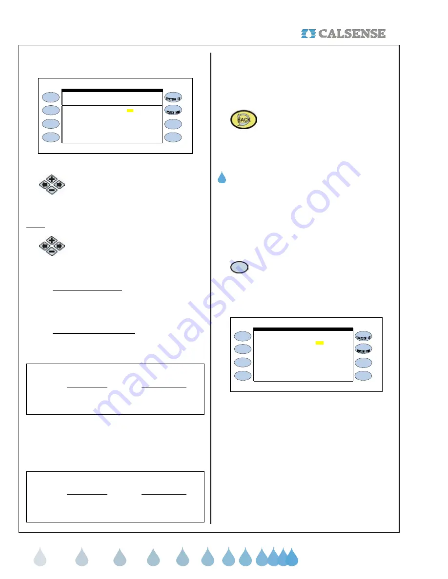
The STATIONS ON-AT-A-TIME screen is displayed
(Figure 4.13).
PROG A . . . . . . . . . . . . . . 1 1
STATIONS ON-AT-A-TIME
Within Within
Program Controller
PROG B . . . . . . . . . . . . . . 1 1
PROG C . . . . . . . . . . . . . . 1 1
An "X" means don't use this
On-At-A-Time as a limit
PROG D . . . . . . . . . . . . . . 1 1
PROG E . . . . . . . . . . . . . . 1 1
DRIP 1 . . . . . . . . . . . . . 1 1
DRIP 2 . . . . . . . . . . . . . 1 1
Figure 4.13
2.
Press the blue
ARROW
keys to move
the cursor to the Program and Within
Program setting desired.
Note:
The default setting is set to 1 on all programs.
3.
To change the settings press the
PLUS
or
MINUS
keys for any number
to change the setting.
•
WITHIN PROGRAM:
This section allows you
to choose the amount of valves that you want
to set as a limit to come on at a time within a
program.
•
WITHIN CONTROLLER:
This section allows
you to choose the amount of valves that you
want to set as a limit to come on at a time
within the controller.
Example:
Within Program Within Controller
Program A 1 2
Program B 1 2
This example allows the user to set up one (1) valve
on at a time for Programs A and B. The controller will
allow both Programs to have one (1) valve each run
simultaneously for a total of two (2) on within
controller.
Example:
Within Program Within Controller
Program A 1 1
Program B 3 3
This example allows the user to set up one (1) valve
on at a time for Programs A. The controller will only
allow one valve to operate while program A is running.
Program B is set up to operate 3 valves on at a time,
and will only operate up to three valves when Program
B is running.
4.
Press the
BACK
key to return to the
FLOW METER, MASTER VALVE, &
PUMP screen (See figure 4.9).
THIS CONCLUDES THE ON AT A TIME SECTION
G. FLOW CHECKING
Flow checking allows you to have the controller
compare the flow of each station during irrigation to
the learned expected flow and alert you of any
problems.
From the FLOW METER, MASTER VALVE & PUMP
SETUP screen (Figure 4.1).
1.
Press the
FLOW CHECKING
Menu
key
The FLOW CHECKING screen is displayed
(Figure 4.14).
flow rate to the expected? NO
FLOW CHECKING
When Irrigating COMPARE the
Figure 4.14
This will open up the ALLOWABLE portion of the
screen when you select YES to the WHEN
IRRIGATING COMPARE THE FLOW TO THE
EXPECTED ? question (Figure 4.15).


