53
12345678901234567890123456789012123456789012345678
12345678901234567890123456789012123456789012345678
12345678901234567890123456789012123456789012345678
12345678901234567890123456789012123456789012345678
12345678901234567890123456789012123456789012345678
12345678901234567890123456789012123456789012345678
12345678901234567890123456789012123456789012345678
12345678901234567890123456789012123456789012345678
12345678901234567890123456789012123456789012345678
12345678901234567890123456789012123456789012345678
12345678901234567890123456789012123456789012345678
12345678901234567890123456789012123456789012345678
12345678901234567890123456789012123456789012345678
12345678901234567890123456789012123456789012345678
PRO FARMER TRIPLEX
PRO FARMER TRIPLEX
PRO FARMER TRIPLEX
PRO FARMER TRIPLEX
PRO FARMER TRIPLEX
PRO FARMER / TS • GENIUS
PRO FARMER / TS • GENIUS
PRO FARMER / TS • GENIUS
PRO FARMER / TS • GENIUS
PRO FARMER / TS • GENIUS
STANDARD FOX
STANDARD FOX
STANDARD FOX
STANDARD FOX
STANDARD FOX
USO E MANUTENZIONE
USO E MANUTENZIONE
USO E MANUTENZIONE
USO E MANUTENZIONE
USO E MANUTENZIONE
OPERATING AND SERVICE
OPERATING AND SERVICE
OPERATING AND SERVICE
OPERATING AND SERVICE
OPERATING AND SERVICE
Rev. 02
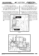
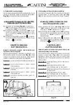
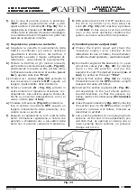
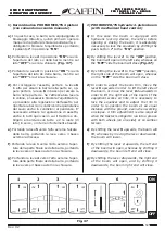
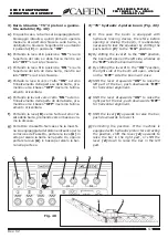
3. Pulizia filtro autopulente
Per procedere alla pulizia del filtro autopulente, con la
pompa in pressione, aprire la valvola di spurgo
(C -
Fig. 29)
per alcuni secondi, poi richiuderla.
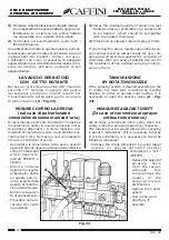
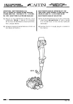
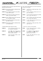
AZIONAMENTI MANUALI SU GRUPPO
COMANDO ELETTROCONTROL
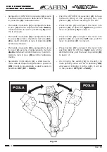
1)
Portando la leva
(A) (Fig.30)
in posizione
“ON”
si alimenta il miscelatore nel serbatoio,
in posizione
“OFF”
lo si esclude.
2)
Portando la leva
(B)
in posizione
“ON”
si ali-
menta il gruppo premixer-lavabarattoli, men-
tre in posizione
“OFF”
tale gruppo viene
disattivato.
3)
Portando la leva
(C)
in posizione si alimen-
ta il getto rotativo lavacisterna, mentre in po-
sizione lo si esclude.
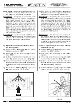
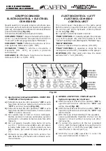
GRUPPO COMANDO
ELETTROCONTROL
Quadro comando valvole motorizzate per
apertura/chiusura getti.
Questo quadro elettrico consente la gestione a di-
stanza delle valvole di sezione
(A - Fig. 31)
, della
valvola di regolazione della pressione, dello scarico
rapido in cisterna e se presente, del tracciafile.
Leva n.1
: apertura/chiusura della parte finale sx.
Leva n.2
: apertura/chiusura della parte
intermedia sx.
Leva n.3
: apertura/chiusura della parte
centrale.
Leva n.4
: apertura/chiusura della parte
intermedia dx.
Leva n.5
: apertura/chiusura della parte fi-
nale dx.
Fig. 30
ON
OFF
A B
C
Fig. 31
A
CAFFINI
1
2
3
4
5
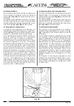
3. Cleaning of the self-cleaning filter
In order to proceed with the cleaning of the self-
cleaning filter, to open the drain valve
(C - Fig.
29)
for few seconds and then to close it again.
MANUAL OPERATIONS ON THE
ELECTROCONTROL UNIT
1)
By shifting the lever
(A) (Fig. 30)
to the
“ON”
position, the mixer in the tank is fed,
whereas in
“OFF”
position it is cutoff.
2)
By shifting the lever
(B)
to the
“ON”
position,
the premixer-can washing device unit is fed,
whereas in
“OFF”
position this unit is
desactivated.
3)
By shifting the lever
(C)
to the position,
the rotating tank washing nozzle is fed,
whereas in position it is cutoff.
CONTROL UNIT
ELETTROCONTROL
Control panel of motor-operated valves for
nozzle opening and closing.
This electric panel allows to remote control the
section valves
(A - Fig. 31)
, the pressure
adjusting valve, the valve for the quick tank
discharge, and , if available, also the row marking
device valve.
Lever Nr. 1
: Opening/closing of the left boom
end.
Lever Nr. 2
: Opening/closing of the left
intermediate part of the boom.
Lever Nr. 3
: Opening/closing of the central part
of the boom.
Lever Nr. 4
: Opening/closing of the right
intermediate part of the boom.
Lever Nr. 5
: Opening/closing of the right boom
end.

