55
12345678901234567890123456789012123456789012345678
12345678901234567890123456789012123456789012345678
12345678901234567890123456789012123456789012345678
12345678901234567890123456789012123456789012345678
12345678901234567890123456789012123456789012345678
12345678901234567890123456789012123456789012345678
12345678901234567890123456789012123456789012345678
12345678901234567890123456789012123456789012345678
12345678901234567890123456789012123456789012345678
12345678901234567890123456789012123456789012345678
12345678901234567890123456789012123456789012345678
12345678901234567890123456789012123456789012345678
12345678901234567890123456789012123456789012345678
12345678901234567890123456789012123456789012345678
PRO FARMER TRIPLEX
PRO FARMER TRIPLEX
PRO FARMER TRIPLEX
PRO FARMER TRIPLEX
PRO FARMER TRIPLEX
PRO FARMER / TS • GENIUS
PRO FARMER / TS • GENIUS
PRO FARMER / TS • GENIUS
PRO FARMER / TS • GENIUS
PRO FARMER / TS • GENIUS
STANDARD FOX
STANDARD FOX
STANDARD FOX
STANDARD FOX
STANDARD FOX
USO E MANUTENZIONE
USO E MANUTENZIONE
USO E MANUTENZIONE
USO E MANUTENZIONE
USO E MANUTENZIONE
OPERATING AND SERVICE
OPERATING AND SERVICE
OPERATING AND SERVICE
OPERATING AND SERVICE
OPERATING AND SERVICE
Rev. 02
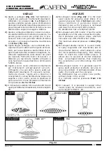
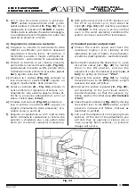
f)
Con le leve di sezione ancora in posizione
“OFF”
, portare la presa di forza a 540 g./min.
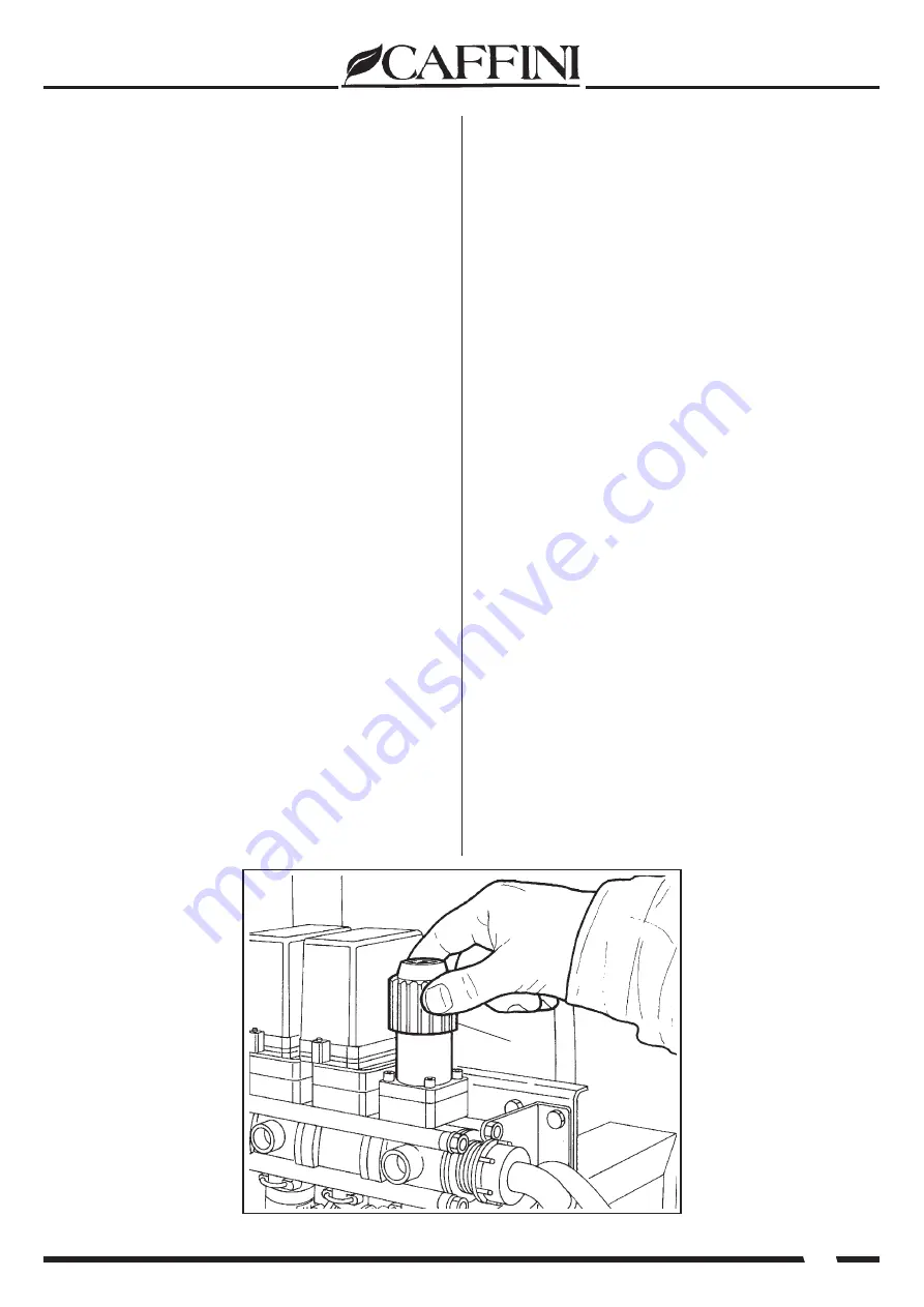
quindi avvitare il pomello
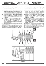
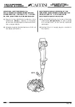
(R - Fig. 34)
fino a
raggiungere la pressione di
15 BAR
in questo,
modo si avrà la certezza che anche nella peggio-
re condizione di lavoro l’impianto non potrà mai
superare la pressione a rischio.
2) Regolazione pressione costante:
a)
Scegliere la velocità di avanzamento della
trattrice e verificare i giri motore necessari
(guardando il libretto istruz. del trattore, il
tachimetro se esiste o meglio verificando di-
rettamente - vedi velocità di avanzamento).
b)
Portare la trattrice ai giri motore prescelti,
aprire tutte le valvole di sezione
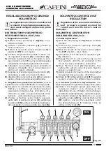
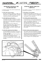
(A - Fig. 32)
,
posizionando le levette su ON, portare infine
l’attrezzatura alla pressione prescelta,
(es. 4
bar)
, agendo sulla leva
“Pres”
.
c)
Chiudere la I sezione
(Fig. 32)
portando la
leva di sezione in posizione
OFF
, seguirà un
leggero innalzamento della pressione.
d)
Svitare il pomello
(B - Fig. 33)
, girando in
senso antiorario il regolatore di sezione cor-
rispondente alla sezione appena chiusa af-
finché la pressione abbassandosi, arrivi al
valore iniziale
(es. 4 bar)
.
e)
Chiudere la II sezione
(Fig. 32)
portando la
leva di sezione in posizione
OFF
, seguirà un
leggero innalzamento della pressione; pro-
cedere come al punto
d
.
f)
Eseguire la regolazione su tutti i settori della
barra. Ultimata la regolazione si noterà che
aprendo o chiudendo uno o più settori della
barra non si avranno variazioni di pressione.
f)
With section levers still in “OFF” position, run
the P.T.O. up to 540 r.p.m., then screw the
knob
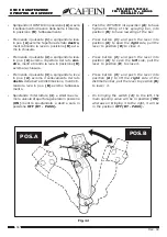
(R - Fig. 34)
until reaching a pressure
of
15 BAR
. In this way we can be sure that
even in the worst operating conditions the
system can never exceed the risk pressure.
2) Constant pressure adjustment:
a)
Choose the tractor speed and check the
necessary engine r.p.m. (looking at the
instructions for use of tractor, the tachometer,
or better by checking directly - see tractor speed).
b)
Run tractor engine at the desired r.p.m., open
all section valves
(A - Fig. 32)
by moving
them to the ON position, and put the
equipment under the desired pressure
(es. 4
bar)
, by acting on the lever
“Pres”
.
c)
Close the first section
(Fig. 32)
by moving
the section lever to the
OFF
position; a slight
pressure increase will follow.
d)
Unscrew the section regulator
(B - Fig. 33)
,
corresponding to the just closed section,
counterclockwise, so that the pessure, by
falling, reaches the initial value
(for instance
4 bar)
.
e)
Close the second section
(Fig. 32)
by moving
the section lever to the
OFF
position; a slight
pressure increase will follow. Proceed as
described in point
d
.
f)
Carry out the adjustment in all spraying boom
sections. At the end of the adjustment, you
will note that, by opening or closing one or
more spraying boom sections, no pressure
change will occure.
Fig. 34
R

