


Order
toll-free
in the U.S. 24 hours, 7 A.M. Monday to midnight Friday:
877-877-BBOX
FREE technical support, 24 hours a day, 7 days a week: Call
724-746-5500
or fax
724-746-0746
Mail order:
Black Box Corporation
, 1000 Park Drive, Lawrence, PA 15055-1018
Web site:
www.blackbox.com
• E-mail:
CUSTOMER
SUPPORT
INFORMATION
OCTOBER 1994
MX219A
MX215C, MX218C
MX222C, MX223C
MX224, MX226C
MX228C, RM220
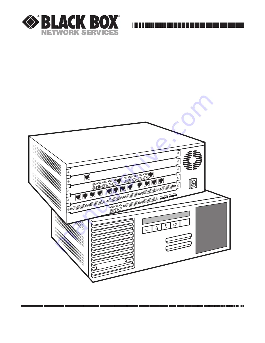
Multiserver 5000
MUL
TISER
VER 5000
EXE


