P/N 133487
37
Banner Engineering Corp.
•
Minneapolis, U .S .A .
www .bannerengineering .com • Tel: 763 .544 .3164
SC22-3 Safety Controller
Instruction Manual
Configuration — PC Interface
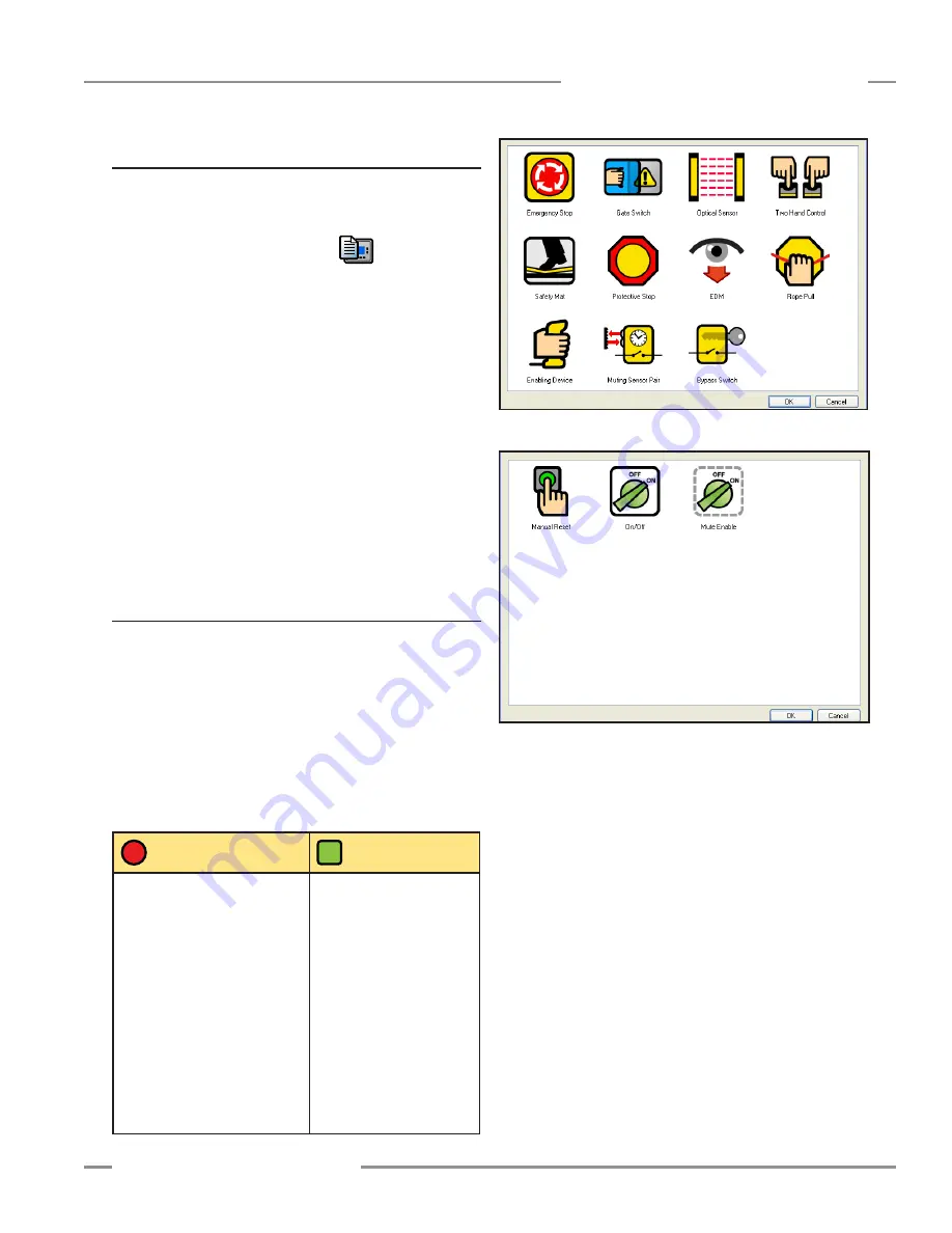
Figure 4-5. Safety Input Device Selection menu
Figure 4-6. Non-Safety Input Device Selection menu
4.3.1 Create a New Configuration
Open the software program, and a new un-named file is created .
You may name the Configuration and the Author, and establish
the system settings at this time .
Double-click the System Settings icon
, on the right-
hand side of the Tool Bar .
When the pop-up menu appears, name the configuration file,
using up to 16 alphanumeric characters .
Add your name in the Author’s name box (up to 10 characters;
abbreviate as needed) .
Keep or change the default system settings:
Power up mode:
Auto, Manual, or Normal (default),
see Section 1 .5 .4
Mute on power up:
ON or OFF (default),
see Section 1 .5 .4
Monitored system reset: OFF or ON (default),
see Section 3 .4
When complete, click OK .
4.3.2 Add an Input Device
Click the Add Safety Input icon and the Safety Input Device
selection menu appears (Figure 4-5) . It displays the device
types the Controller can accommodate . If the non-safety input
icon is clicked, the Non-Safety Input Device selection menu
appears (Figure 4-6) . While their functions differ, the procedure
to add and configure the two types of devices is virtually
identical . Click on the appropriate icon to select the desired
device and click OK (or double-click on the icon) .
NOTE: Refer to Appendix A for more information about each of
the input device types .
Safety Input
Devices
Non-Safety
Input Devices
• Emergency stop button
• Rope pull
• Gate (interlock) switch
• Optical sensor – single-
/multiple-beam sensors, safety
light curtain, area scanners, etc .
• Two-hand control device
• Safety mat
• Protective stop – miscellaneous
devices
• Enabling device
• Muting sensors
• Bypass switches
• External device monitoring
(EDM) contacts
• Manual reset switch
• ON/OFF switch
• Mute enable switch


