


PID Loop Operation
Maintenance
8–23
PID Loop Operation
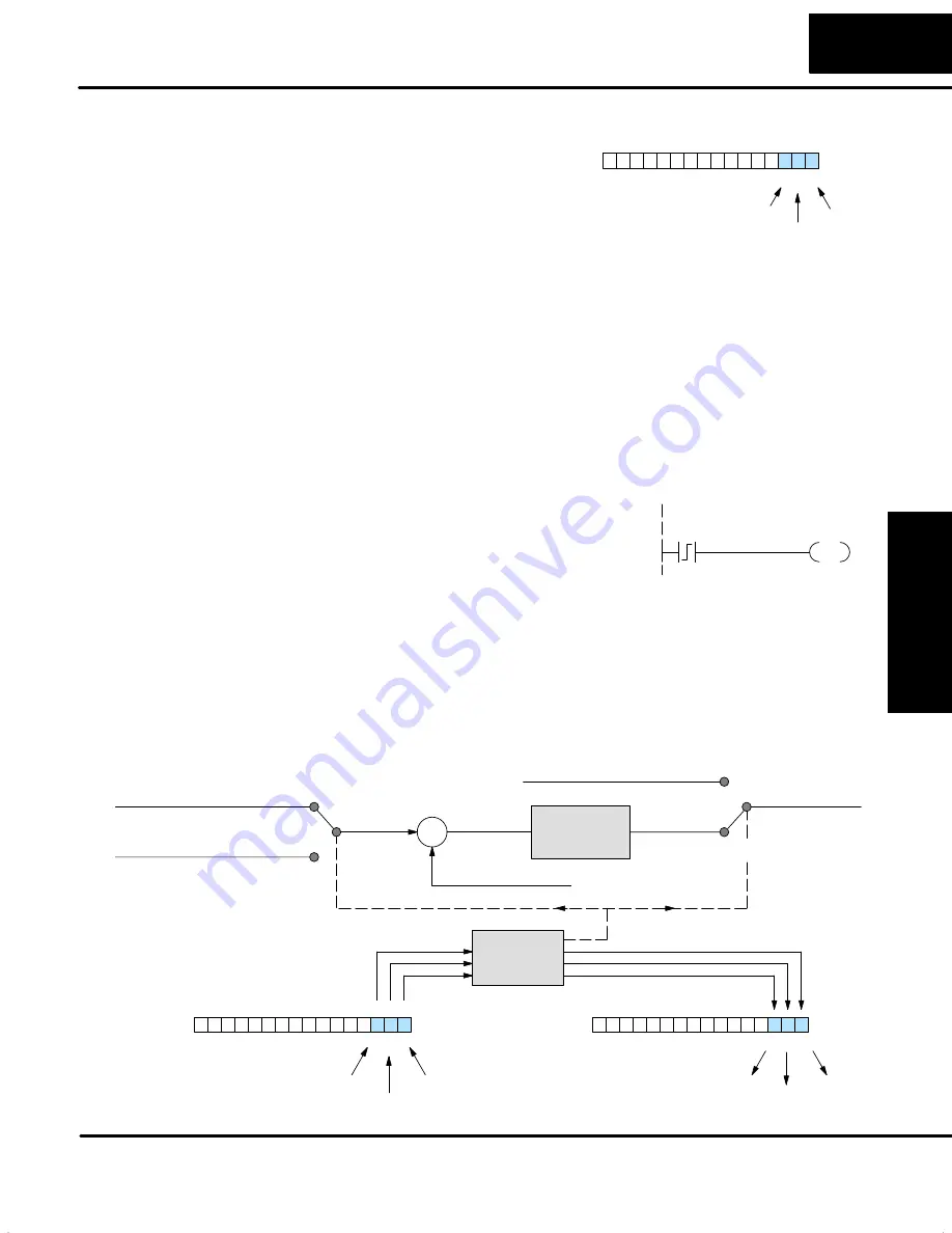
The first three bits of the PID Mode 1 word
(V+00) request the operating mode of the
corresponding loop. Note: these bits are
mode change
requests
, not commands
(certain conditions can prohibit a
particular mode change – see next page).
PID Mode 1 Setting V+00
0
1
3
4
5
6
7
8
9
10
11
12
13
14
15
2
Bit
Automatic
Cascade
Manual
The normal state of these mode request bits is “000”. To request a mode change, you
must SET the corresponding bit to a “1”, for one scan. The PID loop controller
automatically resets the bits back to “000” after it reads the mode change request.
Methods of requesting mode changes are:
S
Direct
SOFT32’s
PID View
– this is the easiest method. Click on one of
the radio buttons, and
Direct
SOFT32 sets the appropriate bit.
S
HPP
– Use Word Status (WD ST) to monitor the contents of V+00,
which will be a 4-digit BCD/hex value. You must calculate and enter a
new value for V+00 that ORs the correct mode bit with its current value.
S
Ladder program
– ladder logic can request any loop mode when the
PLC is in Run Mode. This will be necessary after application startup.
Use the program shown to the right to SET
the mode bit on (do not use an out coil). On
a 0–1 transition of X0, the rung sets the
Auto bit = 1. The loop controller resets it.
X0
SET
B2000.1
Go to Auto Mode
S
Operator panel
– interface the operator’s panel to ladder logic using
standard methods, then use the technique above to set the mode bit.
Since we can only
request
mode changes, the PID loop controller decides when to
permit mode changes and provides the loop mode status. It reports the current mode
on bits 0, 1, and 2 of the Loop Mode and Alarm Status word, location V+06 in the loop
table. The parallel request / monitoring functions are shown in the figure below. The
figure also shows the two possible mode-dependent SP sources, and the two
possible Control Output sources.
Process Variable
S
Error Term
+
–
Input from Operator
Control Output
Setpoint
Manual
Auto/Cascade
Cascade
Auto/Manual
PID Mode 1 Setting V+00
0
1
3
4
5
6
7
8
9
10
11
12
13
14
15
2
Bit
Automatic
Cascade
Manual
Control Output
from another loop
Normal Source
Loop
Calculation
PID Mode
Control
Mode Select
Loop Mode and Alarm Status V+06
0
1
3
4
5
6
7
8
9
10
11
12
13
14
15
2
Bit
Automatic
Cascade
Manual
Mode Request
Mode Monitoring
How to Change
Loop Modes
Содержание DL05
Страница 1: ...DL05 User Manual Automationdirect com ...
Страница 2: ...DL05 User Manual Automationdirect com ...
Страница 436: ...1B DL05 Error Codes In This Appendix Ċ Error Code Table ...
Страница 443: ...1C Instruction Execution Times In This Appendix Ċ Introduction Ċ Instruction Execution Times ...
Страница 459: ...1D Special Relays In This Appendix Ċ DL05 PLC Special Relays ...
Страница 464: ...1E DL05 Product Weights In This Appendix Ċ Product Weight Table ...
Страница 466: ...1F European Union Directives CE In This Appendix Ċ European Union EU Directives Ċ Basic EMC Installation Guidelines ...


