background image

Select objects that enclose an area.

Specify boundary points using the Draw option of -HATCH.

NOTE

Enclosed areas can be hatched only if they are in a plane parallel to the 

XY

plane of the current UCS.

Create Associative Hatches

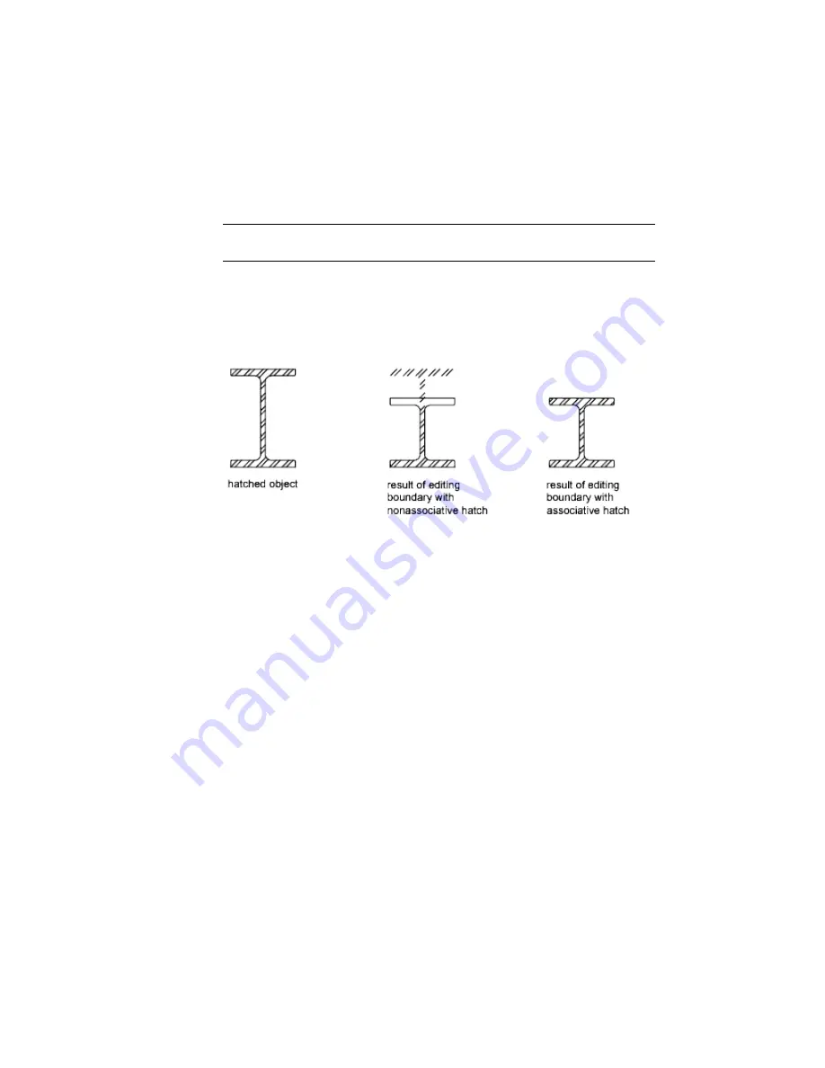
Associative hatches are automatically updated when their boundary objects
are modified. Minor changes in the boundary of an associative hatch do not
require erasing and re-creating the hatch.

Hatch associativity is turned on by default and is controlled by the HPASSOC
system variable. You can also control hatch associativity using the following
tools in the user interface:

Hatch and Gradient dialog box

Hatch Edit dialog box

Hatch visor

Properties Inspector

Nonassociative hatches are not updated when their original boundary is
changed.

Hatch Enclosed Areas Within Boundaries

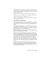
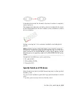
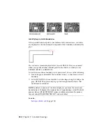
Enclosed areas within hatch boundaries are called islands. There are four island
detection styles available from the user interface:

Normal island detection

Outer island detection (recommended)

Ignore island detection

320 | Chapter 9   Annotate Drawings

Содержание 057B1-41A111-1001 - AutoCAD LT 2010

Страница 1: ...AutoCAD LT 2013 User s Guide January 2012 ...

Страница 2: ...re Flint FMDesktop Freewheel GDX Driver Green Building Studio Heads up Design Heidi Homestyler HumanIK IDEA Server i drop Illuminate Labs AB design logo ImageModeler iMOUT Incinerator Inferno Instructables Instructables stylized robot design logo Inventor Inventor LT Kynapse Kynogon LandXplorer LiquidLight LiquidLight design logo Lustre MatchMover Maya Mechanical Desktop Moldflow Moldflow Plastics...

Страница 3: ...tion from Drawings 4 Obtain General Drawing Information 4 Chapter 2 The User Interface 7 Start a Command 7 Parts of the User Interface 7 The Menu Bar 8 The Tool Sets Palette 8 The Command Line 10 Overview of Using the Command Line 10 Enter Commands on the Command Line 11 Enter System Variables on the Command Line 13 Switch Between Dialog Boxes and the Command Line 14 View and Edit Within the Comma...

Страница 4: ...ning 34 Customize Startup 34 Chapter 3 Start and Save Drawings 37 Start a Drawing 37 Overview of Starting a New Drawing 37 Specify Units and Unit Formats 38 Determine the Units of Measurement 38 Set the Unit Format Conventions 39 Use a Drawing Template File 40 Add Identifying Information to Drawings 41 Open or Save a Drawing 41 Open a Drawing 41 Work with Multiple Open Drawings 44 Preview Open Dra...

Страница 5: ...ing 67 Draw Scale and Annotate in Model Space 68 Create Multiple View Drawing Layouts Paper Space 71 Quick Start for Layouts 71 Understand the Layout Process 71 Work with Model Space and Paper Space 72 Work in Model Space 73 Work on a Named Layout 73 Access Model Space from a Layout Viewport 74 Create and Modify Layout Viewports 75 Control Views in Layout Viewports 76 Scale Views in Layout Viewpor...

Страница 6: ...ith Layer States 113 Work with Colors 116 Set the Current Color 116 Change the Color of an Object 117 Use Color Books 118 Work with Linetypes 119 Overview of Linetypes 119 Load Linetypes 120 Set the Current Linetype 120 Change the Linetype of an Object 121 Control Linetype Scale 122 Display Linetypes on Short Segments and Polylines 123 Control Lineweights 123 Overview of Lineweights 124 Display Li...

Страница 7: ...gle for One Point Angle 156 Combine or Offset Points and Coordinates 157 Combine Coordinate Values Coordinate Filters 157 Track to Points on Objects Object Snap Tracking 160 Track to Offset Point Locations Tracking 162 Specify Distances 162 Enter Direct Distances 162 Offset from Temporary Reference Points 163 Specify Intervals on Objects 163 Extract Geometric Information from Objects 165 Obtain Di...

Страница 8: ...Shape of Objects 227 Fillet Chamfer Break or Join Objects 234 Disassociate Compound Objects Explode 242 Modify Polylines 243 Modify Splines 245 Add Constraints to Geometry 248 Overview of Constraints 248 Constrain Objects Geometrically 251 Overview of Geometric Constraints 251 Apply or Remove Geometric Constraints 252 Display and Verify Geometric Constraints 256 Modify Objects with Geometric Const...

Страница 9: ... Block Attributes 296 Modify a Block Attribute Definition 296 Disassemble a Block Reference Explode 298 Chapter 8 Work with 3D Models 299 Create 3D Models 299 Create Wireframe Models 299 Add 3D Thickness to Objects 301 Chapter 9 Annotate Drawings 303 Work with Annotations 303 Overview of Annotations 303 Scale Annotations 304 Overview of Scaling Annotations 304 Set Annotation Scale 305 Create Annot...

Страница 10: ...Leaders 343 Overview of Leader Objects 343 Create and Modify Leaders 344 Modify Leaders Using Grips 346 Work with Leader Styles 347 Add Content to a Leader 347 Use Fields in Text 350 Insert Fields 350 Update Fields 351 Work with Text Styles 353 Overview of Text Styles 354 Assign Text Fonts 356 Set Text Height 361 Set Text Obliquing Angle 362 Set Horizontal or Vertical Text Orientation 363 Change T...

Страница 11: ...Overview of Geometric Tolerances 424 Material Conditions 426 Datum Reference Frames 426 Projected Tolerance Zones 427 Composite Tolerances 427 Chapter 10 Plot and Publish Drawings 429 Specify Settings for Plotting 429 Save Plot Settings as Named Page Setups 429 Reuse Named Page Setups 430 Specify Page Setup Settings 431 Select a Printer or Plotter for a Layout 431 Select a Paper Size for a Layout ...

Страница 12: ... Files 455 Reference Other Drawing Files 455 Overview of Referenced Drawings Xrefs 455 Attach and Detach Referenced Drawings 456 Attach Drawing References Xrefs 456 Nest and Overlay Referenced Drawings 458 Set Paths to Referenced Drawings 459 Detach Referenced Drawings 461 Update and Archive Referenced Drawings 462 Update Referenced Drawing Attachments 462 Archive Drawings That Contain Referenced ...

Страница 13: ...w of Raster Images 492 Attach Scale and Detach Raster Images 494 Modify Raster Images and Image Boundaries 496 Manage Raster Images 499 Tune Raster Image Performance 501 Export Drawings to Other File Formats 503 Export PDF Files 503 Export DXF Files 503 Export Raster Files 504 Use Drawings from Different Versions and Applications 504 Work with Drawings in Earlier Releases 504 Save Drawings to Prev...

Страница 14: ...s block 525 approximation points 525 array 525 arrowhead 525 aspect ratio 525 associative dimension 525 associative hatch 526 attribute definition 526 attribute extraction file 526 attribute extraction template file 526 attribute prompt 526 attribute tag 526 attribute value 526 axis tripod 526 baseline 526 baseline dimension 527 base point 527 basic tooltip 527 Bezier curve 527 bitmap 527 blips 52...

Страница 15: ...sion 530 control frame 530 control point 530 coordinate filters 530 crosshairs 530 crossing selection 530 CTB file 530 ctrl cycle 531 current drawing 531 cursor 531 cursor menu 531 curve fit 531 custom grips 531 customization CUIx file 531 custom object 531 decimal degrees 531 default 532 default drawing 532 default value 532 definition points 532 definition table 532 dependent named objects in xr...

Страница 16: ...plode 535 exploded dimension 535 extents 535 external reference xref 535 feature control frame 535 fence 535 field 536 fill 536 filters 536 fit points 536 fit tolerance 536 floating viewports 536 font 536 footcandle 536 freeze 536 general property 536 geometric constraint 536 geometry 537 graphics area 537 grid 537 grid limits 537 grip menu options 537 grip modes 537 grips 537 Help menu 538 horizo...

Страница 17: ...l 540 model space 540 model viewports 540 multi functional grip menu options 541 multileader 541 named object 541 named objects dependent 541 named view 541 node 541 non associative dimension 541 noun verb selection 541 object 541 ObjectARX AutoCAD Runtime Extension 541 object enabler 542 Object Snap mode 542 object snap override 542 origin 542 orthogonal 542 Ortho mode 542 page setup 542 palette ...

Страница 18: ...primary table fragment 545 primitive 545 project 545 prompt 545 proxy object 545 QuickView 545 rectangular break 545 redraw 546 reference 546 regenerate 546 region 546 relative coordinates 546 relax constraints 546 RGB 546 row 546 rubber band line 546 running object snap 546 scale representation 547 script file 547 secondary table fragment 547 selection set 547 shortcut keys 547 shortcut menu 547 ...

Страница 19: ...mmand 550 UCS 550 UCS definition 550 UCS icon 550 underconstrained geometry 550 up direction 550 user coordinate system UCS 550 user parameter 551 UVW 551 vector 551 vertex 551 view 551 view category 551 viewpoint 551 viewport 551 viewport configuration 552 virtual screen display 552 WCS 552 window selection 552 wipeout object 552 wireframe model 552 working drawing 552 working set 552 work plane ...

Страница 20: ...zoom 553 xx Contents ...

Страница 21: ...opriate help topic is opened in the Web browser Otherwise the landing page of the Help system is displayed On the Mac OS menu bar click Help AutoCAD LT Help The landing page of the Help system is displayed In a dialog box click the Help or button The help topic related to the dialog box is opened in the Web browser Navigate Help Each page of the help system is divided into four main areas Header C...

Страница 22: ...t box Enter a text string to search on and click the Search button or press Enter to begin the search The results of the search are displayed on a new page The left side of the results page lists the books that a search result was found in while the right side displays the results for the selected book Click a book from the left side to see additional serach results or click a link from the search...

Страница 23: ...er Products Services page for a list of resources available Partner Products and Services for your Autodesk product and your industry View the Product Readme You can find late breaking information about this software in the online Readme It is suggested that you read through the online Readme for the latest information about recommended hardware updated installation instructions and known software...

Страница 24: ...hoose whether you want to start or stop participating 3 Click OK Get Information from Drawings You can retrieve general information from a drawing including identifying information and the number of objects that it contains There are types of information stored in a drawing that are not specific to objects within the drawing but provide useful information to help you understand the behavior of the...

Страница 25: ...unt of time spent in the drawing file See also Enter System Variables on the Command Line page 13 Add Identifying Information to Drawings page 41 Extract Geometric Information from Objects page 165 Compare Dimension Styles and Variables page 379 Get Information from Drawings 5 ...

Страница 26: ...6 ...

Страница 27: ...sed commands Parts of the User Interface The user interface consists of palettes and bars around the drawing area Also several controls are displayed within the drawing area Cmd 1 turns the Tool Sets palette on and off Cmd 2 turns the Content Libraries palette on and off Cmd 3 turns the Command Line on and off 2 7 ...

Страница 28: ...e You can also undock them by dragging and dropping The Menu Bar The menu bar contains common commands organized into logical categories Use the menu bar when learning the product or browsing for a command Many but not all commands are accessible from the menu bar Less commonly used commands can be entered at the Command prompt All available commands are listed in the Help system under Command Ref...

Страница 29: ...outs Some of the tools on the Tool Sets palette have a flyout indicator Click and hold the flyout to display several options for that command Tool Groups The tools on the Tool Sets palette are organized into tool groups Click the arrow to display the entire tool group which includes additional commands To make the tool group stay visible click the lock icon at the bottom of the tool group Start a ...

Страница 30: ...the Tool Sets palette with commands associated with dimensioning Cmd 1 turns the Tool Sets palette on and off TIP Use the Customize dialog box to customize any tool set or create your own tool sets The Command Line The Command Line provides a fast way to enter commands and system variables directly using the keyboard Overview of Using the Command Line The Command Line is not displayed by default b...

Страница 31: ... this method for speed Also the Command Line displays prompts and error messages Cmd 3 turns the Command Line on and off Enter Commands on the Command Line You can enter a command by using the keyboard Some commands also have abbreviated names called command aliases To enter a command by using the keyboard type the full command name or its command alias in the input area of the Command Line and th...

Страница 32: ...stead of entering circle to start the CIRCLE command you can enter c Command aliases are defined in the acadlt pgp file To define your own command aliases see Create Command Aliases in the Customization Guide Specify Command Options When you enter a command in the Command Line you see either a set of options a dialog box or a palette To specify an option displayed in the Command line enter the cap...

Страница 33: ... turn off features For example the GRIDMODE system variable turns the grid display on and off when you change the value Control the operation of a command For example the HPASSOC syatem variable controls whether hatch patterns are associative by default Retrieve stored information about the current drawing and about the program configuration For example CDATE is a read only system variable that st...

Страница 34: ...Suppressing a dialog box is useful for familiar operation with earlier versions of the program and for using script files There may be slight differences between the options in the dialog box and those available in the Command Line These system variables also affect the display of dialog boxes ATTDIA controls whether the INSERT command uses a dialog box for entering block attribute values EXPERT c...

Страница 35: ...g with the next command enter the LOGFILEON command Work with Shortcut Menus Display a shortcut menu for quick access to commands that are relevant to your current activity Shortcut menus can be used to Display the controls for a user interface element such as a palette or the status bar Control the command in progress including command options object snaps and canceling Display a list of recent i...

Страница 36: ... or collapses the display of the Command Window Fn F2 Toggles object snap mode on and off Fn F3 Toggles isoplane mode between top right and left isometric planes Fn F5 Toggles grid display on and off Fn F7 or Control E Toggles ortho mode on and off Fn F8 or Cmd L or Shift Cmd O Opens or closes the Tool Sets palette Cmd 1 Opens or closes the Content palette on and off Cmd 2 Shows or hides the Comma...

Страница 37: ...lays the Find and Replace dialog box Cmd F Groups the selected objects Cmd G Opens or closes the Properties Inspector palette Cmd I Toggles ortho mode on and off Cmd L or Control L Minimizes the current drawing window Cmd M Displays the Select Template dialog box Select a template to create a new drawing Cmd N or Control N Displays the Select File dialog box Select a drawing file to open Cmd O or ...

Страница 38: ...selected from the drawing and adds them to the Clipboard Cmd X or Control X Reverses the most recent undo Cmd Y or Control Y Undoes the most recent action Cmd Z or Control Z Zooms the drawing out by 5 times Cmd Zooms the drawing in by 2 times Cmd Displays the Application Preferences dialog box Cmd Displays the Quick View dialog box Cmd Toggles group selection mode on and off Shift Cmd A Displays t...

Страница 39: ... Displays the Save Drawing As dialog box Shift Cmd S Toggles object snap tracking on and off Shift Cmd T Reverses the most recent undo Shift Cmd Z Displays the Check Spelling dialog box Shift Cmd Selects all objects in the current layout Control A Toggles grid snap mode on and off Control B Copies the selected objects to the Clip board Control C Toggles grid display on and off Control E Toggles ob...

Страница 40: ...ntrol O Displays the Print dialog box and creates a hard copy or PDF file of the current layout Control P Closes the program Control Q Saves the current drawing If the drawing has not been saved yet the Save Drawing As dialog box is displayed Control S Toggles polar tracking on and off Control U Pastes the contents of the Clipboard to the current layout Control V Removes the selected from the draw...

Страница 41: ...f Shift Control A Toggles grid snap mode on and off Shift Control B Copies the selected objects to the Clipboard with a specified base point Shift Control C Toggles object snap mode on and off Shift Control F Toggles grid display on and off Shift Control G Repeats the previous command Shift Control J Repeats the previous command Shift Control M Toggles ortho mode on and off Shift Control O Display...

Страница 42: ...refer a white or a black background color depending on their tasks and preferences See also Set Up the Drawing Area page 32 Interface Themes and Background Color To change the color of the user interface between dark and light 1 On the menu bar click AutoCAD LT 2013 and then Preferences 2 In the Application Preferences dialog box left column click Look Feel 3 Under Interface Theme click in the The...

Страница 43: ...a combination of the crosshairs and pickbox cursors If you are prompted to enter text the cursor appears as a vertical bar In the following illustrations these cursors are displayed in order You can change the size of the crosshairs and pickbox cursors in the Application Preferences dialog box by clicking Cursor Selection the OPTIONS command Selection Style Selecting objects conforms to a selectio...

Страница 44: ...d dragging the icon using the grips that are displayed The UCS is useful because it controls features that include The angular orientation that defines horizontal and vertical The alignment and angle of the grid and hatch patterns The origin and orientation for 2D and 3D coordinate entry You can change the appearance of the UCS icon with the UCSICON command Properties option With this command you ...

Страница 45: ... input is turned on For more information about dynamic input see Use Dynamic Input page 144 See also Use Dynamic Input page 144 Overview of Coordinate Entry Model Space and Layouts There are two working environments or spaces in which you can work model space and paper space layouts Model space is used to create 2D drawings Paper space is used create layouts for plotting While you can plot from mo...

Страница 46: ...awing or selected objects and insert blocks or hatch patterns from custom content libraries The Status Bar The Status bar includes buttons that turn on and off various features For example this is where you can conveniently turn on and off the grid display grid snap object snap dynamic input and so on The status bar also includes controls to display lineweights and object transparency Several cont...

Страница 47: ...ff The Status Bar To control the display of buttons on the status bar 1 Right click any empty area of the status bar 2 In the status bar menu click Display and then any flyout 3 Click any button name in the flyout to change whether it is displayed or hidden The Layers Palette The Layers palette is used to display and manage layers and layer groups The disclosure triangle in the Layers palette expa...

Страница 48: ...or a selected layer as a vertical list To switch from displaying object properties click the Layer Properties tab at the top of the Properties Inspector palette Display Layer Groups Layer groups are displayed in the Layer list and allow you to group layers together by what they represent in the drawing or similar layer properties Grouping layers together allows you to change the layer status of al...

Страница 49: ...e click the Create Layer button which looks like a stack of papers 3 Enter the name of the new layer in the highlighted text area and then press Enter To change the current layer 1 On the Layers palette click the Layer drop down 2 Click the layer that you want to make the current layer There are several alternative methods In the expanded Layers palette you can right click a layer to display a men...

Страница 50: ... of the current layer The key to controlling the information that appears in the Properties Inspector is choosing either the Object Current tab or the Layer Properties tab in the top left corner of the palette For object properties clicking either the Essentials button or the All button controls the number of properties displayed Object Current Properties Tab The Properties Inspector with the Obje...

Страница 51: ...ess and manage content libraries From the Content palette you can Create custom content libraries to organize frequently used blocks Add and remove blocks from the Favorites library or a custom library Insert blocks from the current drawing Favorites library or a custom library Content Libraries Libraries are used to help organize and access the blocks that you frequently use By default there is n...

Страница 52: ...adjust the application interface and drawing area to match the way you work Set Up the Drawing Area You can adjust the color and display schemes used in the application and drawing windows and control the behavior of general features such as grip editing behavior Many of the settings are available from shortcut menus and the Application Preferences dialog box Some user interface elements such as t...

Страница 53: ...e Behavior of Palettes Palettes such as Tool Set status bar and Reference Manager can be docked displayed as icons or floated Settings for these and other options are often changed on a shortcut menu available by right clicking the title bar of the palette Resize Drag an edge of the palette to change its size If one or more palettes are docked dragging one of the palettes adjusts the size of the o...

Страница 54: ...lay driver Enable these features at your own risk For information on the options available see 3DCONFIG Graphics Caching Graphics cache files are created and maintained to optimize performance and increase the regeneration speed of objects with complex geometry such as 3D solids non mesh surfaces and regions These cache files persist between drawing sessions and are saved in Users user name Librar...

Страница 55: ... used to set up drawing parameters in a new drawing file Creates a new drawing based on a template or prototype drawing Template file name t The syntax for using command line switches is pathname AutoCAD LT drawingname switchname When using a switch option you must follow the switch with a space and then the name of a file For example the following entry starts the program from a folder named Auto...

Страница 56: ...36 ...

Страница 57: ...r those drawing units Choose Drawing Units A drawing unit can equal one inch one millimeter or any other system of measurement For more information about drawing units see Determine the Units of Measurement page 38 Choose a Drawing Template File When you start a new drawing AutoCAD LT accesses a drawing template file to determine many default settings such as unit precision dimension styles layer ...

Страница 58: ...nit represents based on what you plan to draw You can convert a drawing between systems of measurement by scaling it Every object you create is measured in drawing units Before you start to draw you must decide what one drawing unit will represent based on what you plan to draw Then you create your drawing at actual size with that convention For example the objects in the illustration might repres...

Страница 59: ...n the Properties Inspector palette dynamic input the status bar and other locations For example here are three variations of dynamic input Set Angular Units You can specify that positive values of angles are measured either clockwise or counterclockwise and the direction of angle 0 usually East or North You can enter angles using grads radians or surveyor s units or using degrees minutes and secon...

Страница 60: ...es is installed with AutoCAD LT Many of them are provided either for imperial or for metric units and some are optimized for 3D modeling All drawing template files have a dwt file extension While these drawing templates provide a quick way to start a new drawing it is best to create drawing templates specific to your company and the type of drawings you create Create a Drawing Template File When y...

Страница 61: ...on a certain date or for files you modified yesterday Display Properties in Fields You can assign any of the drawing properties to a field in a text object For more information about fields see Use Fields in Text page 350 Open or Save a Drawing You can use several methods to find and open drawings even damaged drawings You can save and backup drawings automatically Open a Drawing You open drawings...

Страница 62: ...e drawings and you want to begin working immediately To take advantage of this capability three conditions are required The drawing must have been saved in paper space The INDEXCTL system variable must be set to a non zero value When these conditions are met you can create or modify visible objects pan or zoom turn off or freeze layers and any other operation that does not require displaying objec...

Страница 63: ...n the folder with the drawing or one of the support paths defined in the Application Preferences dialog box Work with Large Objects AutoCAD LT 2010 supports object size limits greater than those available in previous releases With increased object size limits you can create larger and more complex models Using increased object size limits can result in compatibility issues with legacy drawing file...

Страница 64: ...iew you can easily preview and switch between open drawings and layouts in an open drawing The Show Drawings Layouts button on the status bar allows you to do the following Open drawings All open drawings are displayed along the left side of the QuickView dialog box Double click a drawing thumbnail to switch to the corresponding drawing file or right click a drawing thumbnail to display a list of ...

Страница 65: ...n the Current Drawing Switch between the model space and layouts in the current drawing You can use one of the following methods to switch between layouts in the current drawing On the status bar click the Show Drawings Layouts button In the QuickView dialog box click the layout thumbnail on the right side On the status bar click the Drawings Layouts pop up menu and choose a layout from the middle...

Страница 66: ...or use on a network The character limit for a DWG file name including its path is 256 characters NOTE If the FILEDIA system variable is set to 0 the Command prompt version displays instead of a file navigation dialog box Save Part of a Drawing File If you want to create a new drawing file from part of an existing drawing you use the WBLOCK command With the command you can select objects or specify...

Страница 67: ...CAD LT 2008 and later releases in AutoCAD LT 2007 and earlier releases When this option is not selected a single model space representation is displayed on the Model layout More annotation objects may be displayed on the Model layout depending on the ANNOALLVISIBLE setting Also more objects may be displayed in paper space viewports at different sizes than in AutoCAD LT 2008 and later releases Redu...

Страница 68: ...th Large Object Limits Drawings saved to a legacy drawing file format AutoCAD LT 2007 or earlier do not support objects greater than 256MB With the AutoCAD LT 2010 drawing file format these limitations have been removed allowing you to save objects that are greater in size When saving to a legacy drawing file format AutoCAD LT 2007 or earlier the drawing cannot contain large objects there might be...

Страница 69: ...Files Internationally page 516 Open and Save Drawing Files from the Internet page 516 Find a Drawing File You can search for a drawing using name location and date filters Use Searchlight in Finder to search for drawings using name location and date filters Use the Select File dialog box for the OPEN command to display drawing file previews When the RASTERPREVIEW system variable is on a raster pre...

Страница 70: ...pen files on a CD specify a different location for your temporary files The temporary folder that you specify must not be write protected and the drive containing the folder should have sufficient disk space for the temporary files It is recommended that you manually delete the files from this folder on a regular basis to ensure sufficient space is provided for temporary files If not enough space ...

Страница 71: ...tes a description of problems with a drawing file and recommendations for correcting them As you start the audit you specify whether you want the program to try to fix the problems it encounters The report is similar to the following example Auditing Header DXF NAME Current Value Validation Default PDMODE 990 2040 UCSFOLLOW 811 or 0 Error found in auditing header variables 4 Blocks audited Pass 1 ...

Страница 72: ...ackup version by renaming the bak file in Finder to a file with a dwg extension You may want to copy it to a different folder to avoid overwriting your original file Save Your Drawing Automatically at Specified Intervals If you turn the automatic save option on your drawing is saved at specified time intervals By default files saved automatically are temporarily assigned the name filename_a_b_nnnn...

Страница 73: ... Files Recovered dialog box Be sure to save your work after you begin and regularly thereafter For each drawing you can open and choose from the following files if they exist DrawingFileName dwg DrawingFileName bak DrawingFileName_a_b_nnnn sv NOTE The drawing backup and recover files are listed in the order of their time stamps the time when they were last saved If you close the Files Recovered di...

Страница 74: ...ed You can also add other information such as what you were doing at the time of the error The REPORTERROR system variable controls whether the error reporting feature is available 54 Chapter 3 Start and Save Drawings ...

Страница 75: ...oving your pointing device Like panning with a camera PAN does not change the location or magnification of objects on your drawing it changes only the view You can change the magnification of a view by zooming in and out which is similar to zooming in and out with a camera ZOOM does not change the absolute size of objects in the drawing it changes only the magnification of the view When you work w...

Страница 76: ... the Realtime option you zoom dynamically by moving your pointing device up or down By right clicking you can display a shortcut menu with additional viewing options Zoom to Magnify One or More Objects ZOOM Objects displays a view with the largest possible magnification that includes all of the objects you selected Zoom to View All Objects in the Drawing ZOOM Extents displays a view with the large...

Страница 77: ...t and plotting or when you need to refer to specific details A named view created with the VIEW command consists of a specific magnification position and orientation In each drawing session you can restore up to 10 previous views displayed in each viewport using ZOOM Previous Named views are saved with a drawing and can be used any time When you are composing a layout you can restore a named view ...

Страница 78: ... viewports restore a different view in each one Control the 3D Projection Style You can view both parallel and perspective projection of a 3D model Define a Parallel Projection You can define a parallel projection To determine the point or angle in model space you can Enter a coordinate or angles that represent your viewing location in 3D Change to a view of the XY plane of the current UCS a saved...

Страница 79: ...metric View If you move toward the upper right corner of the box you are viewing it from NE Isometric View Define a 3D View with Coordinate Values or Angles You can define a viewing direction by entering the coordinate values of a point or the measures of two angles of rotation This point represents your position in 3D space as you view the model while looking toward the origin 0 0 0 Viewpoint coo...

Страница 80: ...ting the UCS orientation to World and then setting the 3D view to Plan View Hide Lines or Shade 3D Objects You can create a hidden line representation or a simple shaded picture of the objects displayed in the current viewport Hide Lines in 3D Objects Suppress the display of objects partly or entirely that are located behind other objects in three dimensional views You can create a hidden line rep...

Страница 81: ...ned off but not frozen can also hide other objects You can adjust how hidden lines are displayed by changing the settings in the Hidden Line Settings dialog box Display Views with Hidden Lines Removed For viewing you can temporarily suppress hidden lines with HIDE HIDE suppresses all hidden lines in a view When the view is regenerated all objects are displayed normally See also Set Options for Plo...

Страница 82: ...ding options 256 Color Creates shaded faces with no edge highlighting You need a 256 color display to see the full effect of this option 256 Color Edge Highlight Creates shaded faces with edges highlighted in the background color You need a 256 color display with the program s standard 256 color map to see the full effect of this option 16 Color Hidden Line Simulates a hidden line display The face...

Страница 83: ... known as model space viewports Viewports are areas that display different views of your model As you work on the Model layout you can split the drawing area into one or more adjacent rectangular views known as model space viewports In large or complex drawings displaying different views reduces the time needed to zoom or pan in a single view Also errors you might miss in one view may be apparent ...

Страница 84: ...ayouts Paper Space page 71 Use Model Space Viewports With model space viewports you can do the following Pan zoom set Snap Grid and UCS icon modes and restore named views Draw from one viewport to another when executing a command Name a viewport arrangement so that you can reuse it on the Model layout or insert it on a named layout Split and Join Model Space Viewports The illustrations below show ...

Страница 85: ...two model space viewports you start the line in the current viewport make another viewport current by clicking within it and then specify the endpoint of the line in the second viewport In a large drawing you can use this method to draw a line from a detail in one corner to a detail in a distant corner Save and Restore Model Layout Viewport Ar rangements Arrangements of model viewports can be save...

Страница 86: ...tings for each viewport The UCS icon display setting for each viewport You can list restore and delete the available viewport arrangements A viewport arrangement saved on the Model layout can be inserted on a named layout 66 Chapter 4 Control the Drawing Views ...

Страница 87: ... Drafting The process of creating and plotting a drawing file in model space is very different from the process used in manual drafting In AutoCAD LT there are two distinct working environments that are represented by Model and named layouts If you are going to create a two dimensional drawing that has one view you can create both the model and its annotation entirely in model space not using a la...

Страница 88: ... for the drawing Specify the display style for the drawing unit Calculate and set the scale for dimensions annotations and blocks Draw at full scale 1 1 in model space Create the annotation and insert the blocks in model space Print the drawing at the predetermined scale You can also use objects if you want to scale annotations automatically For information about using annotative objects and scali...

Страница 89: ...es Set the scale for noncontinuous linetypes with the CELTSCALE and LTSCALE system variables Hatch patterns Set the scale for hatch patterns while creating the hatch HATCH before creating the hatch object with the HPSCALE system variable or edit the hatch after it has been created Blocks Specify the insertion scale for blocks either as you insert them or set an insertion scale in the Insert Block ...

Страница 90: ...ectural scale ratios in the table can be used to calculate text sizes in model space Set drawing text size to To plot text size at Scale factor Scale 30 cm 3 mm 100 1 cm 1 m 12 1 8 96 1 8 1 0 8 1 8 64 3 16 1 0 6 1 8 48 1 4 1 0 4 1 8 32 3 8 1 0 3 1 8 24 1 2 1 0 2 1 8 16 3 4 1 0 1 5 1 8 12 1 1 0 1 0 1 8 8 1 1 2 1 0 If you are working in metric units you might have a sheet size of 210 x 297 mm A4 siz...

Страница 91: ...rking in model space you draw a model of your subject at 1 1 scale Working on a named layout you create one or more layout viewports dimensions notes and a title block to represent a drawing sheet Each layout viewport is like a picture frame containing a photograph of the model in model space Each layout viewport contains a view that displays the model at the scale and orientation that you specify...

Страница 92: ...emplate that already has a title block Create a new layer to be used for layout viewports Create layout viewports and position them on the layout Set the orientation scale and layer visibility of the view in each layout viewport Add dimensions and annotate in the layout as needed Turn off the layer containing the layout viewports Output your layout You can also use annotative objects if you want t...

Страница 93: ...ents the actual distance on a sheet of paper The units will be in either millimeters or inches depending on how you configure your page setup On a named layout you can view and edit paper space objects such as layout viewports and title blocks You can also move an object such as a leader or a title block from model space to paper space or vice versa The crosshairs cursor is active over the entire ...

Страница 94: ...ts in the layout viewport are restored NOTE If you use PLOT while a viewport is maximized the layout is restored before the Print dialog box is displayed If you save and close the drawing while a viewport is maximized the drawing opens with the named layout restored If you choose to switch to the default model space to make changes the layer visibility settings are the settings for the drawing as ...

Страница 95: ...ties and also scale and move them as needed NOTE It is important to create layout viewports on their own layer When you are ready to output your drawing you can turn off the layer and output the layout without the boundaries of the layout viewports With MVIEW you have several options for creating one or more layout viewports You can also use COPY and ARRAY to create multiple layout viewports Creat...

Страница 96: ...oundary of a layout viewport by using the VPCLIP command You can either select an existing object to designate as the new boundary or specify the points of a new boundary The new boundary does not clip the old boundary it redefines it A nonrectangular viewport consists of two objects the viewport itself and the clipping boundary You can make changes to the viewport the clipping boundary or both NO...

Страница 97: ...for a quarter scale drawing the ratio would be a scale factor of one paper space unit to four model space units or 1 4 Scaling or stretching the layout viewport border does not change the scale of the view within the viewport When creating a new drawing based on a template the scales in the template are used in the new drawing The scales in the user profile are not imported Lock the Scale of Layou...

Страница 98: ...box For more information about annotation scaling see Scale Annotations page 304 Control Visibility in Layout Viewports You can control the visibility of objects in layout viewports using several methods These methods are useful for emphasizing or hiding different elements of a drawing and for reducing screen regeneration time See also Display Annotative Objects page 314 Freeze Specified Layers in...

Страница 99: ...ll new viewports If you create a viewport that requires dimensions you can override the default setting by changing the setting in the current viewport Changing the default for new viewports does not affect existing viewports Create New Layers That Are Frozen in All Layout Viewports You can create new layers that are frozen in all existing and new layout viewports Then you can thaw the layers in t...

Страница 100: ...ning some layout viewports off or by limiting the number of active viewports Displaying a large number of active layout viewports can affect your system s performance as the content of each layout viewport regenerates You can save time by turning some layout viewports off or by limiting the number of active viewports The following illustration shows the effects of turning off two layout viewports ...

Страница 101: ...ines should appear to be the same If you change the viewport zoom factor to 2x the linetype scaling for the dashed line in the layout and the dashed line in the layout viewport will be the same regardless of the difference in the zoom factor With PSLTSCALE turned on you can still control the dash lengths with LTSCALE and CELTSCALE In the following illustration the pattern of the linetypes in the d...

Страница 102: ...views on a layout with precision you can create construction geometry use object snaps on the model space objects displayed in layout viewports or use one of the drafting aids on the status bar Rotate Views in Layout Viewports You can rotate an entire view within a layout viewport with the VPROTATEASSOC system variable 82 Chapter 5 Organize Drawings and Layouts ...

Страница 103: ...ply the information from an existing template A layout template is a layout imported from a DWG or DWT file When you create a layout you can choose to apply the information from an existing template The program has sample layout templates to use when you design a new layout environment The paper space objects and page setup in the existing template are used in the new layout Thus the layout object...

Страница 104: ...le items are not saved with the file they are not added to the new layout into which you import the template If you insert a layout from a drawing or template that was not created using the Save As option of the LAYOUT command definition table items that are used in the drawing but not in the layout are inserted with the layout To eliminate unnecessary definition table items use the PURGE command ...

Страница 105: ...reate organize and manage layouts in a project You use the following features in the Project Manager Project Popup Menu Lists all the open and recently opened projects Use the list to switch between open projects Publish Project Button Displays and populates the Batch Publish dialog box with all the layouts in the current project Project Tree View Displays an organized list of all layouts in the c...

Страница 106: ...roject Switch to the Model tab when opening a drawing associated with a layout Show who currently has a project or layout locked Controls the renaming of drawing files and layouts when changing name and numbers in the Project Manager Actions Available in the Project Tree View You can use the following actions in the tree view Double click layouts to open the associated drawing Right click to acces...

Страница 107: ...u begin creating a project you should complete the following tasks Consolidate drawing files Move the drawing files to be used in the project into a small number of folders This will simplify administration of managing the project and its files Eliminate multiple layout tabs Each drawing you plan to use in the project should have only one layout This is important for access to layouts when multipl...

Страница 108: ...ject dialog box when you choose to create a project from an existing DST file the project provides the organizational structure only for the new project The properties are set to their default values and no layouts are added from the existing project Backup and Recover Project Data Files The data stored in the sheet set data file represents a significant amount of work so you should take the same ...

Страница 109: ...ate When you place views in this layout the drawing files associated with the views are attached as xrefs Modify a layout Double click a layout on the Project tree view to open the associated drawing To review a layout right click on the layout and click Open Layout Read only to open the drawing in read only mode NOTE Modifying a layout should always be done using an open project in the Project Ma...

Страница 110: ...the layout and view that are referenced NOTE When you place a callout block with fields on a layout make sure that the current layer is unlocked Create Callout Blocks and Label Blocks Advanced If you create a block to be used as a callout block or label block in a project you can use a placeholder field to display information such as view title or layout number The callout or label block must be d...

Страница 111: ...oject Manager below the layout they are placed on Named model space views cannot be placed on a layout with the Project Manager However you can edit the properties of a view and place view label blocks for a view on a layout that has already been placed If you modify the geometry in a drawing that contains the referenced named view the changes are displayed on the layout as long as the changed geo...

Страница 112: ...Owners Projects groups layouts and views represent different levels of organization and each of the items includes different types of properties You specify the values for these properties after you create the project group layout or view In addition you can define custom properties for a project and layout The values for custom properties for a project are typically specific to just that project ...

Страница 113: ...PDF in either normal or reverse order If you select a layout to publish only that layout is added to the Batch Publish dialog box Selecting a group adds all the layouts in that group to the Batch Publish dialog box while selecting the project name adds all layouts in the project to the dialog box You can exclude a layout or group from being published by changing the values of the Include for Publi...

Страница 114: ...e being saved back When the DST file is opened and being edited a lock icon appears below the Project popup menu Adjacent to the lock icon is the name of the user currently editing the file in the format of In use by user name The lock icon appears under the following situations Properties of the project a group a layout or a view in the project are being edited A layout is being created or added ...

Страница 115: ...l in your session when a command is active You can click any layout to display more information in the Details panel of the Project Manager NOTE A false lock icon may be displayed if there is a network problem or if the program terminates unexpectedly If you suspect a problem click the layout to display more information Work in a Team That Does Not Use Project Manager With some limitations you can...

Страница 116: ...tion to the drawing and drawing template files referenced by the project file you need to make sure the following are also accessible to all users Drawing template DWT files Callout blocks View label blocks Page setups Project Terminology Differences The terminology used on AutoCAD for Windows is different from that on the Mac OS X Description Windows Term Mac OS X Term User interface used to acce...

Страница 117: ...rom a drawing file and assigned to a project sheet layout A group of layouts in a pro ject that is often organized subset group by discipline or workflow stage A named model space view placed on a layout sheet view named view Work with Layouts in a Project 97 ...

Страница 118: ...98 ...

Страница 119: ...as properties Some properties are general and apply to most objects for example layer color linetype transparency and plot style Other properties are object specific for example the properties of a circle include radius and area and the properties of a line include length and angle Most general properties can be assigned to an object by layer or can be assigned to an object directly When a propert...

Страница 120: ...ed the Properties Inspector palette displays only those properties common to all objects in the selection set When no objects are selected the Properties Inspector palette displays only the general properties of the current layer the name of the plot style table attached to the layer the view properties and information about the UCS Control Double Click Behavior You can double click most objects t...

Страница 121: ...perty or properties to be copied use the Settings option to suppress the copying of that property You can choose the Settings option at any time during the command Work with Layers Layers are like transparent overlays on which you organize and group objects in a drawing Overview of Layers Layers are used to group information in a drawing by function and to enforce linetype color and other standard...

Страница 122: ...g includes a layer named 0 Layer 0 cannot be deleted or renamed It has two purposes Ensure that every drawing includes at least one layer Provide a special layer that relates to controlling colors in blocks NOTE It is recommended that you create several new layers with which to organize your drawing rather than create your entire drawing on layer 0 Use Layers to Manage Complexity You can use layer...

Страница 123: ...y cause the drawing to be regenerated Freezing and thawing layers takes more time than turning layers on and off In a layout you can freeze layers in individual layout viewports NOTE Instead of turning off or freezing a layer you can fade the layer by locking it See Lock the Objects on a Layer below Control Transparency on Layers Set the transparency of layers and layout viewports to enhance drawi...

Страница 124: ... and gray for the other you easily accomplish this objective without changing the global color property assigned to the layer See Override Layer Properties in Viewports page 107 for more information Lock the Objects on a Layer When a layer is locked none of the objects on that layer can be modified until you unlock the layer Locking layers reduces the possibility of modifying objects accidentally ...

Страница 125: ...rs palette sorts layers alphabetically by name If you organize your own layer scheme choose layer names carefully Use common prefixes to name layers with related drawing components this makes it easier to locate and manipulate groups of layers at a time NOTE If you consistently use a specific layering scheme you can set up a drawing template with layers linetypes and colors already assigned For mo...

Страница 126: ...r to another Change the name of a layer Change the default color linetype or other properties of the layer Reassigning an object to a different layer is useful if you create an object on the wrong layer or decide to change your layer organization Unless the color linetype or other properties of the object have been set explicitly an object that you reassign to a different layer will acquire the pr...

Страница 127: ... restore it Added layers If you add a new layer to a drawing using Layer Previous does not remove it Override Layer Properties in Viewports You can display objects differently by setting property overrides for color linetype lineweight transparency and plot style and apply them to individual layout viewports Using property overrides is an efficient way for displaying objects with different propert...

Страница 128: ... Plot Style available only in named plot style drawings When a property override is set for a layer a Viewport Overrides layer group is automatically created in the Layers palette If you do not want to display or plot property overrides set the VPLAYEROVERRIDESMODE system variable to 0 Objects will display and plot with their global layer properties NOTE Property overrides can still be set even wh...

Страница 129: ...isplays a Layer Property Overrides field The value that displays is the same as the setting for VPLAYEROVERRIDES Remove Layer Property Overrides When you right click a layer in the Layers palette a shortcut menu is displayed that lists options for removing property overrides You can remove A single property override from the selected layer for the selected viewport or for all selected viewports Al...

Страница 130: ... Viewport Overrides If there are layers with overrides for the current viewport displays all layers containing property overrides Unreconciled Layers If new layers were added since the drawing was last opened saved reloaded or plotted displays a list of new unreconciled layers See Reconcile New Layers page 113 for more information NOTE The default layer groups cannot be renamed edited or deleted O...

Страница 131: ...explicitly assign to it If the properties of the layers assigned to the layer group change the layers are still part of the layer group Static layer groups can only be nested under other static layer groups TIP Layers from the Layer list can be included added to a layer group by clicking and dragging the selected layers to the layer group Invert a Layer Group You can invert the layers displayed by...

Страница 132: ...matches all strings that don t contain AB tilde Matches any one of the characters enclosed for example AB C matches AC and BC Matches any character not enclosed for example AB C matches XC but not AC Specifies a range for a single character for example A G C matches AC BC and so on to GC but not HC Reads the next character literally for example AB matches AB reverse quote NOTE To filter on a layer...

Страница 133: ... new Layers that are added after a drawing is first saved are considered new unreconciled layers NOTE The layer baseline is created when the LAYEREVAL system variable is set to 1 or 2 When a command that is set in the LAYERNOTIFY system variable is used the layer list is checked at that time and compared to the baseline If there are new layers the Unreconciled Layers layer group is automatically c...

Страница 134: ...the viewport that contains overrides is active If the layer state is saved from model space any layer property override settings are not included This is because only one value can be saved for each layer property in a layer state If layer property overrides need to be saved in the layer state make the viewport active on the layout tab and then save the layer state Restore Layer Settings When you ...

Страница 135: ...ed or unloaded Import and Export Layer States You can import layer settings from other drawings DWG and DWT and export layer states LAS If the layer state is imported from a drawing and it contains a layer property such as a linetype or plot style that is not loaded or available in the current drawing that property is automatically imported from the source drawing If the layer state is imported fr...

Страница 136: ...ts including AutoCAD LT Color Index ACI True Color PANTONE Colors RAL Classic and RAL Design color books DIC Color Guide Colors from imported color books ACI Colors ACI colors are the standard colors used in AutoCAD LT Each color is identified by an ACI number an integer from 1 through 255 Standard color names are available only for colors 1 through 7 The colors are assigned as follows 1 Red 2 Yel...

Страница 137: ...ng color 7 white or black until the objects are grouped into a block When the block is inserted into the drawing it acquires the current color setting PANTONE Color Books Pantone has updated the PANTONE MATCHING SYSTEM with the PANTONE PLUS SERIES of Publications that provides a chromatic arrangement of colors In AutoCAD based products the RGB values of the PANTONE Colors that are assigned to obje...

Страница 138: ...a wide range of custom colors when using color books Color books include third party or user defined files that contain named color swatches These colors can be used to enhance presentation drawings as well as to optimize the variety of color used in your drawings You can apply color book colors to objects in your drawings by using the Color Books tab in the Color Palette dialog box Install Color ...

Страница 139: ...eating pattern of dashes dots and blank spaces displayed in a line or a curve You assign linetypes to objects either by layer or by specifying the linetype explicitly independent of layers In addition to choosing a linetype you can set its scale to control the size of the dashes and spaces and you can create your own custom linetypes NOTE These linetypes should not be confused with the hardware li...

Страница 140: ...l or metric measurements For imperial units use the acadlt lin file For metric measurements use the acadltiso lin file Both linetype definition files contain several complex linetypes If you select a linetype whose name begins with ACAD_ISO you can use the ISO pen width option when you plot You can remove unreferenced linetype information with PURGE or by deleting the linetype from the Linetype Ma...

Страница 141: ...layer with a different linetype If an object s linetype is set to BYLAYER and you reassign the object to a different layer it acquires its linetype from the new layer Change the linetype assigned to the layer that the object is on If an object s linetype is set to BYLAYER it acquires the linetype of its layer When you change the linetype assigned to a layer all objects on that layer assigned the B...

Страница 142: ...re displayed as continuous You can use a smaller linetype scale for lines that are too short to display even one dash sequence The Linetype Manager displays the Global Scale Factor and Current Object Scale The Global Scale Factor value controls the LTSCALE system variable which changes the linetype scale globally for both new and existing objects The Current Object Scale value controls the CELTSCA...

Страница 143: ...u can accommodate short segments by using a smaller value for their individual linetype scales For more information see Control Linetype Scale page 122 For polylines you can specify whether a linetype pattern is centered on each segment or is continuous across vertices throughout the entire length of the polyline You do this by setting the PLINEGEN system variable Control Lineweights You can contr...

Страница 144: ...ith a real world width of 0 5 inches do not use a lineweight instead use a polyline with a width of 0 5 inches to represent the object You can also plot objects in your drawing with custom lineweight values Use the Plot Style Table Editor to adjust the fixed lineweight values to plot at a new value Lineweight Scale in Drawings Objects with a lineweight are plotted with the exact width of the assig...

Страница 145: ...Space Lineweight display in model space does not change with the zoom factor For example a lineweight value that is represented by a width of four pixels is always displayed using four pixels regardless of how far you zoom in If you want the lineweights on objects to appear thicker or thinner on the Model layout use LWEIGHT to set their display scale Changing the display scale does not affect the ...

Страница 146: ...t to be the lineweight assigned to the current layer you can specify a different lineweight explicitly Objects in drawings created in an earlier release of AutoCAD LT are assigned the lineweight value of BYLAYER and all layers are set to DEFAULT Lineweight assigned to objects is displayed as a solid fill drawn in the object s assigned color Change the Lineweight of an Object You can change the lin...

Страница 147: ...ewports page 107 Control the Display Properties of Certain Ob jects You can control how overlapping objects and certain other objects are displayed and plotted Control the Display of Polylines Hatches Gradient Fills Lineweights and Text You can simplify the display of certain kinds of objects in order to speed performance Display performance is improved when wide polylines and donuts solid filled ...

Страница 148: ...weights off You can turn lineweights on and off by choosing the Show Hide Lineweight button on the status bar Lineweights are always plotted at their real world value whether their display is turned on or off Update the Display New objects automatically use the current settings for displays of solid fill and text Except for lineweights to update the display of existing objects using these settings...

Страница 149: ...set to ByLayer ByBlock or to a specific value IMPORTANT For performance reasons plotting transparency is disabled by default To plot transparent objects check the Plot Transparency option in either the Print dialog box or Page Setup dialog box Control How Overlapping Objects Are Displayed You can change the draw order which is the display and plotting order of any objects that you select You can u...

Страница 150: ...If you isolate objects only the isolated objects appear in the view Use UNISOLATEOBJECTS to redisplay the objects When you close and reopen the drawing all previously hidden objects are displayed Use the OBJECTISOLATIONMODE system variable to control whether objects remain hidden between drawing sessions Use Precision Tools You can use a variety of precision drawing tools to help you produce accur...

Страница 151: ...in a new drawing However it is usually more convenient to create and edit objects based on the UCS which can be customized to suit your needs Understand the UCS Icon The UCS icon indicates the location and orientation of the current UCS You can manipulate the UCS icon using grips For more information see The UCS Icon page 24 and the UCSICON command NOTE If the location of the UCS origin is not vis...

Страница 152: ...the location and orientation of the UCS the UCS icon is displayed either at the UCS origin point or in the lower left corner of the current viewport You can choose a 2D or 3D style of the icon to represent the UCS when working in 2D environment Shaded style of icon is displayed to represent the UCS in the 3D environment Use the UCSICON command to choose between displaying the 2D or the 3D UCS icon...

Страница 153: ...n the viewing direction is in a plane parallel to the UCS XY plane The broken pencil icon indicates that the edge of the XY plane is almost perpendicular to your viewing direction This icon warns you not to use your pointing device to specify coordinates When you use the pointing device to locate a point it s normally placed on the XY plane If the UCS is rotated so that the Z axis lies in a plane ...

Страница 154: ... the XY plane also called the work plane The work plane is similar to a flat sheet of grid paper The X value of a Cartesian coordinate specifies horizontal distance and the Y value specifies vertical distance The origin point 0 0 indicates where the two axes intersect Polar coordinates use a distance and an angle to locate a point With both Cartesian and polar coordinates you can enter absolute co...

Страница 155: ...vertical axis Absolute coordinates are based on the UCS origin 0 0 which is the intersection of the X and Y axes Use absolute coordinates when you know the precise X and Y values of the point With dynamic input you can specify absolute coordinates with the prefix If you enter coordinates on the command line instead of in the tooltip the prefix is not used For example entering 3 4 specifies a point...

Страница 156: ...t specified The following example draws the sides of a triangle The first side is a line starting at the absolute coordinates 2 1 and ending at a point 5 units in the X direction and 0 units in the Y direction The second side is a line starting at the endpoint of the first line and ending at a point 0 units in the X direction and 3 units in the Y direction The final line segment uses relative coor...

Страница 157: ...oordinates using the following format x y Enter Polar Coordinates You can use absolute or relative polar coordinates distance and angle to locate points when creating objects To use polar coordinates to specify a point enter a distance and an angle separated by an angle bracket By default angles increase in the counterclockwise direction and decrease in the clockwise direction To specify a clockwi...

Страница 158: ...n angle of 45 degrees from the X axis For more information about dynamic input see Use Dynamic Input page 144 The following example shows two lines drawn with absolute polar coordinates using the default angle direction setting Enter the following in the tooltip Command line From point 0 0 To point 4 120 To point 5 30 Relative coordinates are based on the last point entered Use relative coordinate...

Страница 159: ...a prompt for a point enter coordinates in the tooltip using the following format distance angle If dynamic input is turned off enter coordinates on the command line using the following format distance angle To enter relative polar coordinates 2D At a prompt for a point enter coordinates using the following format distance angle Enter 3D Coordinates Cartesian cylindrical or spherical coordinates lo...

Страница 160: ... the command line With dynamic input you specify absolute coordinates with the prefix In the illustration below the coordinate values of 3 2 5 indicates a point 3 units along the positive X axis 2 units along the positive Y axis and 5 units along the positive Z axis Use Default Z Values When you enter coordinates in the format X Y the Z value is copied from the last point you entered As a result y...

Страница 161: ...y Enter 3D Cartesian Coordinates To enter absolute coordinates 3D At a prompt for a point enter coordinates in the tooltip using the following format x y z If dynamic input is turned off enter coordinates on the command line using the following format x y z To enter relative coordinates 3D At a prompt for a point enter coordinates using the following format x y z Enter Cylindrical Coordinates 3D c...

Страница 162: ...in of the current UCS 30 degrees from the X axis in the XY plane and 6 units along the Z axis When you need to define a point based on a previous point rather than the UCS origin you can enter relative cylindrical coordinate values with the prefix For example 4 45 5 specifies a point 4 units in the XY plane from the last point entered at an angle of 45 degrees from the positive X direction and ext...

Страница 163: ...ngle from the X axis in the XY plane and its angle from the XY plane each angle preceded by an open angle bracket as in the following format X angle from X axis angle from XY plane NOTE For the following examples it is assumed that dynamic input is turned off or that the coordinates are entered on the command line With dynamic input you specify absolute coordinates with the prefix In the following...

Страница 164: ... display information near the cursor that is dynamically updated as the cursor moves When a command is active the tooltips provide a place for user entry After you type a value in an input field and press Tab the field then displays a lock icon and the cursor is constrained by the value that you entered You can then enter a value for the second input field Alternately if you type a value and press...

Страница 165: ...t sign If you want to use absolute coordinates use the pound sign prefix For example to move an object to the origin for the second point prompt enter 0 0 Use the pointer input settings to change the default format for coordinates and to control when pointer input tooltips are displayed Dimensional Input When dimensional input is on the tooltips display distance and angle values when a Command pro...

Страница 166: ...tive angle direction Dynamic Prompts When dynamic prompts are on prompts are displayed in a tooltip near the cursor You can enter a response in the tooltip instead of on the command line Press the Down Arrow key to view and select options Press the Up Arrow key to display recent input NOTE To use paste text into a dynamic prompt tooltip type a letter and then backspace to delete it before you past...

Страница 167: ...ompt for a point you can When prompted for a point right click and choose an object snap from the Snap Overrides sub menu Enter the name of an object snap at the Command prompt On the status bar right click the object snap button When you specify an object snap at a prompt for a point the object snap stays in effect only for the next point that you specify NOTE Object snaps work only when you are ...

Страница 168: ...valent button on another pointing device You can also right click while being prompted for a point and click Snap Overrides See also Use Object Snaps page 147 Set Visual Aids for Object Snaps AutoSnap Object snaps include a visual aid called AutoSnap to help you see and use object snaps more efficiently AutoSnap displays a marker and a tooltip when you move your cursor over an object snap location...

Страница 169: ...r example if you have set running object snaps but you want to turn them off for one point you can hold down Fn F3 When you release this override key running object snaps are restored There are also temporary override keys for individual object snaps Override keys are set up to be easy to find by touch without looking away from your drawing The keys in the following illustration are the default ke...

Страница 170: ... drawing aids that you set in the Drafting Settings dialog box See also Adjust Grid and Grid Snap page 151 Use Orthogonal Locking Ortho Mode page 153 Use Polar Tracking and PolarSnap page 154 Use Dynamic Input page 144 150 Chapter 6 Create and Modify Objects ...

Страница 171: ...r the pointing device Grid mode and Snap mode are independent but are often used in combination with each other Control the Display Style and Area of the Grid You can display the grid either as a rectangular pattern of dots or as rectangular pattern of lines The grid displays dots when SHADEMODE is set to 2D Wireframe The grid displays lines when SHADEMODE is set to Hidden The LIMITS command contr...

Страница 172: ...rid will not display SNAPANG does not affect the display of the dotted grid Change the Grid Dynamically During Zooming If you zoom in or out of your drawing the grid spacing is adjusted automatically to be more appropriate for the new magnification This is called adaptive grid display For example if you zoom way out the density of displayed grid lines reduces automatically Conversely if you zoom w...

Страница 173: ...alignment or angle you can change the grid and snap angle by rotating the user coordinate system UCS This rotation realigns the crosshairs on the screen to match the new angle In the following example the UCS is rotated 30 degrees to match the angle of the anchor bracket The grid and snap points are always aligned with the UCS origin If you need to shift the grid and grid snap origin move the UCS ...

Страница 174: ...key Shift While you use the temporary override key the direct distance entry method is not available For drawing or editing objects at angles that are not parallel to the horizontal or vertical axis see Use Polar Tracking and PolarSnap page 154 If turned on the isometric snap setting takes priority over the UCS in determining horizontal and vertical directions NOTE Ortho mode and polar tracking ca...

Страница 175: ...ursor alignment paths and tooltips are displayed when you move the cursor near polar angles The default angle measurement is 90 degrees Use the alignment path and tooltip to draw your object You can use polar tracking with Intersection and Apparent Intersection object snaps to find where a polar alignment path intersects another object NOTE Ortho mode and polar tracking cannot be on at the same ti...

Страница 176: ... to lengths of 0 4 8 12 16 and so on As you move your cursor a tooltip indicates the nearest PolarSnap increment To restrict point entry to polar distances both polar tracking and Snap mode set to PolarSnap must be on You can turn off all snapping and tracking temporarily by using an override key See also Override Object Snap Settings page 149 Lock an Angle for One Point Angle You can specify an a...

Страница 177: ...ate location by using the X value from one location the Y value of a second location and for 3D coordinates the Z value of a third location When used with object snaps coordinate filters extract coordinate values from an existing object Coordinate filters are commonly used to locate the center of a rectangle and to locate the projection of a 3D point on the XY plane of the UCS To specify a filter ...

Страница 178: ...ate filter at the Command prompt you see an error message Example Use of Coordinate Filters in 3D This example shows how to use coordinate filters to create a point object at the center centroid of a 3D object Hidden lines have been removed for clarity The X value of the new point is extracted from the first location specified the Y value from the second location and the Z value from the third The...

Страница 179: ...a point in 3D 1 At the prompt for a point enter a coordinate filter x y z xy xz or yz For example enter x to specify the X value first 2 To extract the specified coordinate value s specify a point For example if you entered x in step 1 the X value is extracted from this point 3 At the prompt for the remaining coordinates do one of the following Extract the remaining coordinate values by specifying...

Страница 180: ...ject snap before you can track from an object s snap point Object Snap Tracking Use object snap tracking to track along alignment paths that are based on object snap points Acquired points display a small plus sign and you can acquire up to seven tracking points at a time After you acquire a point horizontal vertical or polar alignment paths relative to the point are displayed as you move the curs...

Страница 181: ...ar End and Mid object snaps with object snap tracking to draw to points that are perpendicular to the end and midpoints of objects Use the Tangent and End object snaps with object snap tracking to draw to points that are tangent to the endpoints of arcs Use object snap tracking with temporary tracking points At a point prompt enter tt then specify a temporary tracking point A small appears at the ...

Страница 182: ... reference point You can track as many points as you need Typically you use tracking in combination with object snaps or direct distance entry For example you can use tracking to find the center point of a rectangle without using construction lines Start tracking and specify the midpoint of a horizontal line Drag the cursor vertically and specify the midpoint of a vertical line 2 Press Enter to ac...

Страница 183: ... for One Point Angle page 156 Offset from Temporary Reference Points You can establish a temporary reference point as a base point for offsetting subsequent points The From command modifier establishes a temporary reference point as a base point for offsetting subsequent points The From method does not constrain the cursor to orthogonal movement The From method usually is used in combination with ...

Страница 184: ...ual lengths from one end of a selected object You can use MEASURE to mark an object at specified intervals You can mark the intervals with either points or blocks The last segment of a measured object may be shorter than the interval you specify The starting point for measurements or divisions varies with the object type For lines or open polylines the starting point is the endpoint closest to the...

Страница 185: ...p angle For example if the snap angle is 0 the circle starts at the three o clock position and continues counterclockwise If the point marker is displayed as a single dot the default setting you may not be able to see the segments You can change the style of the point markers with the Point Style dialog box DDPTYPE The PDMODE system variable also controls the appearance of point markers For exampl...

Страница 186: ...ea perimeter and mass properties defined by selected objects or a sequence of points You can calculate the area and perimeter of a sequence of points You can also obtain the area perimeter and mass properties of any of several types of objects TIP A fast way to calculate an area bounded by several objects in 2D is to use the BOUNDARY command With BOUNDARY you can pick a point within the area to cr...

Страница 187: ...closed region defined by the points you specify The points must lie on a plane parallel to the XY plane of the current UCS Calculate the Area Perimeter or Circumference of an Object You can calculate the enclosed area and perimeter or circumference of circles ellipses polylines polygons regions and AutoCAD 3D solids The information displayed depends on the type of object selected Circles Area and ...

Страница 188: ...ned Areas Calculate Combined Areas You can calculate the total area of multiple areas by specifying points or by selecting objects For example you can measure the total area of selected rooms in a floor plan 168 Chapter 6 Create and Modify Objects ...

Страница 189: ...h step The Command prompt sequence is Command area Specify first corner point or Object Add area Subtract area Object a Specify first corner point or Object Subtract area o ADD mode Select objects Select the polyline 1 Area 0 34 Perimeter 2 71 Total area 0 34 ADD mode Select objects Press Enter Specify first corner point or Object Subtract area s Specify first corner point or Object Add area o SUB...

Страница 190: ...n use the CAL command at the Command prompt transparently while a command is active or not Use the Command Prompt Calculator By entering an expression in the Command prompt calculator you can quickly solve a mathematical problem or locate points in your drawing The CAL command runs the 3D calculator utility to evaluate vector expressions combining points vectors and numbers and real and integer ex...

Страница 191: ...on Operator Groups expressions Indicates numeric exponent Multiplies and divides numbers Adds and subtracts numbers Calculating Points You can use CAL whenever you need to calculate a point or a number within a command For example you enter mid cen 2 to specify a point halfway between the midpoint of a line and the center of a circle The following example uses CAL as a construction tool It locates...

Страница 192: ...L expression At a prompt for a command in progress enter CAL to start the CAL command transparently Then enter a CAL expression to calculate a value for that prompt Create Objects Drawings are made up of objects In general you draw objects by specifying points with the pointing device or by entering coordinate values at the Command prompt You can create a range of objects from simple lines and cir...

Страница 193: ...enter of a circle as one endpoint of the line Turn grid snap on and snap to a location There are other methods for creating precise lines A highly efficient technique is to offset a line from an existing line and then trim or extend it to the desired length Use polyline objects instead of line objects if you want the segments to be connected as a single object See also Enter Coordinates to Specify...

Страница 194: ...ate a polyline you can edit it using grips or PEDIT You can use EXPLODE to convert polylines to individual line and arc segments NOTE You can convert a spline fit polyline created with PEDIT into a true spline object with SPLINE Create Wide Polylines You can draw polylines of various widths by using the Width and Halfwidth options You can set the width of individual segments and make them taper gr...

Страница 195: ...omplex drawings you can specify a group of boundary candidates called a boundary set You create this set by selecting the objects you want to use define the boundary See also Draw Rectangles and Polygons page 175 Modify Objects page 206 Break and Join Objects page 241 Control Lineweights page 123 Draw Rectangles and Polygons You can create rectangles and regular polygons quickly Creating polygons ...

Страница 196: ...KETCH command Freehand sketches comprise many line segments that are converted into a line polyline or spline For Splines you can determine how closely the spline s curve fits to the freehand sketch For any sketch type set the minimum length increment of the line segments Small line segments allow greater accuracy but they can greatly increase the drawing file size Before sketching check the CELTY...

Страница 197: ...rection values You can create arcs in several ways With the exception of the first method arcs are drawn counterclockwise from the start point to the endpoint Draw Arcs by Specifying Three Points You can create an arc by specifying three points In the following example the start point of the arc snaps to the endpoint of a line The second point of the arc snaps to the middle circle in the illustrat...

Страница 198: ...options you can specify either the start point first or the center point first Draw Arcs by Specifying Start Center Angle You can create an arc using a start point center and an included angle The distance between the start point and the center determines the radius The other end of the arc is determined by specifying an included angle that uses the center of the arc as the vertex The resulting ar...

Страница 199: ...is determined by specifying the length of a chord between the start point and the endpoint of the arc The resulting arc is always created counterclockwise from the start point Using different options you can specify either the start point first or the center point first The length of the chord of the arc determines the included angle Draw Arcs by Specifying Start End Angle You can create an arc us...

Страница 200: ...the arc is determined by the order in which you specify its endpoints You can specify the radius either by entering it or by specifying a point at the desired radius distance Draw Contiguous Tangent Arcs and Lines Immediately after you create an arc you can start a line that is tangent to the arc at an endpoint by starting the LINE command and pressing Enter at the Specify First Point prompt You n...

Страница 201: ...cify the center and the radius Three other ways to draw a circle are shown in the illustration Draw a Circle Tangent to Other Objects The tangent point is a point where an object touches another object without intersecting it To create a circle that is tangent to other objects select the objects and then specify the radius of the circle In the illustrations below the bold circle is the one being d...

Страница 202: ...ht line segments arc segments or a combination of the two Multisegmented lines provide editing capabilities unavailable for single lines For example you can adjust their width and curvature After you ve created a polyline you can edit it with PEDIT or use EXPLODE to convert it to individual line and arc segments You can Convert a spline fit polyline into a true spline with SPLINE Use closed polyli...

Страница 203: ...h and Halfwidth options set the width of the next polyline segments you draw Zero 0 width produces a thin line Widths greater than zero produce wide lines which are filled if Fill mode is on and outlined if Fill mode is off The Halfwidth option sets width by specifying the distance from the center of the wide polyline to an outside edge Taper When you use the Width option you are prompted for both...

Страница 204: ...fine the boundary See also Modify Splines page 245 Modify Polylines page 243 Break and Join Objects page 241 Control Lineweights page 123 Draw Donuts Donuts are filled rings or solid filled circles that actually are closed polylines with width To create a donut you specify its inside and outside diameters and its center You can continue creating multiple copies with the same diameter by specifying...

Страница 205: ...ecifying axis and distance The third point specifies only a distance and does not necessarily designate the axis endpoint If you are drawing on isometric planes to simulate 3D you can use ellipses to represent isometric circles viewed from an oblique angle First you need to turn on Isometric Snap in the Drafting Settings dialog box DSETTINGS command See also Draw Isometric Circles page 522 Break a...

Страница 206: ...e strips that are shaped by weights at data points In the following example SPLINE was used to create the highlighted boundary of the concrete walkway BLEND was used to create splines between lines and arcs for a golf course design The resulting splines are tangent to the selected lines and curves without changing the lengths of the selected objects Understand Control Vertices and Fit Points You c...

Страница 207: ...ntrol vertices to fit points automatically changes the selected spline to degree 3 Splines originally created using higher degree equations will likely change shape as a result Create Splines Using Control Vertices When you create splines using control vertices the points you specify display temporary lines between them forming a control polygon that determines the shape of the spline The advantag...

Страница 208: ...erization is commonly used and the square root centripetal parameterization often produces better curves depending on the data set When the Tolerance value is set to 0 the spline passes directly through the fit points With larger tolerance values the spline passes near the fit points Optionally you can specify the tangent direction for the spline at each end NOTE The fit point method always result...

Страница 209: ... closure is marked with a dot The result of setting the SPLPERIODIC system variable to periodic is shown on the left while the result of the legacy setting is shown on the right NOTE The legacy method for creating B splines by creating a polyline and then using the Spline option of the PEDIT command generates only an approximate spline fit polyline See also Modify Splines page 245 Break and Join O...

Страница 210: ...ooming or viewpoints and they are ignored by commands that display the drawing extents You can move rotate and copy infinite lines just as you can move rotate and copy other objects You may want to create infinite lines on a construction line layer that can be frozen or turned off before plotting Construction Lines A construction line also known as xlines can be placed anywhere in three dimensiona...

Страница 211: ...on line Rays A ray is a line in three dimensional space that starts at a point you specify and extends to infinity Unlike construction lines which extend in two directions rays extend in only one direction Using rays instead of construction lines can help reduce visual clutter Like construction lines rays are ignored by commands that display the drawing extents Create and Combine Areas Regions Reg...

Страница 212: ...ical arcs and splines that enclose an area You create regions using the REGION command to convert a closed object into a region and the BOUNDARY command to create a region from an area enclosed by objects You can combine regions by unifying subtracting or intersecting them Objects combined using UNION Objects combined using SUBTRACT Objects combined using INTERSECT 192 Chapter 6 Create and Modify ...

Страница 213: ...y or by using REDRAW REGEN or REGENALL Create Revision Clouds Revision clouds are polylines that consist of sequential arcs They are used to call attention to parts of a drawing during the review stage If you review or redline drawings you can increase your productivity by using the Revision Cloud feature to highlight your markups REVCLOUD creates a polyline of sequential arcs to form a cloud shap...

Страница 214: ...f a revision cloud by adjusting the pick points REVCLOUD stores the last used arc length as a multiple of the DIMSCALE system variable to provide consistency among drawings with different scale factors Make sure that you can see the entire area to be outlined with REVCLOUD before you begin the command REVCLOUD is not designed to support transparent and real time panning and zooming Select and Modi...

Страница 215: ...ion two lines and a circle lie within the pickbox If selection preview is turned on you can cycle through the objects by rolling over the object on top to highlight it or you can press and hold Shift and then press the Spacebar When the required object is highlighted left click to select it If selection preview is turned off hold down Shift and Spacebar at a Select Objects prompt while you left cl...

Страница 216: ...ion Drag your cursor from left to right to select only objects that are entirely enclosed by the rectangular area Crossing selection Drag your cursor from right to left to select objects that the rectangular window encloses or crosses With a window selection usually the entire object must be contained in the rectangular selection area However if an object with a noncontinuous dashed linetype is on...

Страница 217: ...e and selects only the objects it passes through The circuit board illustration shows a fence selecting several components Use Other Selection Options You can see all selection options by entering at the Select Objects prompt For a description of each of the selection options see SELECT Remove Selection from Multiple Objects You can enter r Remove at the Select Objects prompt and use any selection...

Страница 218: ...can do the following Hover over an object to see whether a lock icon is displayed Dim the objects on locked layers NOTE Grips are not displayed on objects that are on locked layers Select Objects by Properties Use object properties or object types to include objects in a selection set or to exclude them To quickly define a selection set based on specified filtering criteria use Select Similar SELE...

Страница 219: ... choose Whether objects to be selected are previewed during selection Whether selected objects are highlighted How you define selection areas and how you create selection sets Select the Command First When you use an editing command a Select Objects prompt is displayed and the crosshairs is replaced with a pickbox You can respond to the Select Objects prompt in various ways Select objects one at a...

Страница 220: ...rned on by default You can turn them off with the SELECTIONPREVIEW system variable When the PICKBOX system variable is set to 0 selection previewing of objects is not available Control the Appearance of Selected Objects By default selected objects are displayed with dashed lines You can increase program performance by setting the HIGHLIGHT system variable to 0 Turning off selection highlighting do...

Страница 221: ...pulate as a unit You can create them quickly and with a default name You can change the components of groups as you work by adding or removing objects In some ways groups resemble blocks which provide another method of combining objects into a named set For example groups are saved from session to session However you can edit individual objects in groups more easily than you can edit them in block...

Страница 222: ...ct Objects in Groups There are several methods for choosing a group including selecting the group by name or selecting one of the members of the group By default groups are selectable that is selecting any member of a group selects all the objects in that group You can then edit the group as a unit Selecting an object that belongs to multiple groups selects all groups to which that object belongs ...

Страница 223: ...group does not automatically add the resulting components to any group Remove Groups You can delete a group definition to ungroup the contained objects As a result objects are ungrouped but not otherwise changed Correct Mistakes You can backtrack your recent actions using one of several methods Undo a Single Action The simplest method of backtracking is to use the UNDO or U commands to undo a sing...

Страница 224: ...o list on the Standard toolbar Erase Objects You can erase any object that you draw If you accidentally erase the wrong object you can use the UNDO command or the OOPS command to restore it For more information see Erase Objects page 204 Cancel a Command You can cancel a command without completing it by pressing Esc Erase Objects There are many ways to delete objects from your drawing and clean up...

Страница 225: ...or copy these objects to the Clipboard and then paste them from the Clipboard into the other application Cut Objects Cutting deletes selected objects from the drawing and stores them on the Clipboard The objects are now available to be pasted into other programs Copy Objects You can use the Clipboard to copy part or all of a drawing into a document created by another application The objects are co...

Страница 226: ...n object to display a shortcut menu with relevant editing op tions Shortcut menu Double click an object to display the Prop erties Inspector palette or in some cases a Double click dialog box or editor that is specific to that type of object Use grips to reshape move rotate and manipulate objects Grips Grip modes Select an object grip to work with the default grip mode stretch or press Enter or Sp...

Страница 227: ...ther ways using different types of grips and grip modes Overview You can use grips in different ways Use grip modes Select an object grip to work with the default grip mode stretch or press Enter or Spacebar to cycle through the additional grip modes move rotate scale and mirror You can also right click a selected grip to see all available options on a shortcut menu Use multi functional grips For ...

Страница 228: ...des however any object or grip specific options are not available Tips for Stretching with Grips When you select more than one grip on an object to stretch it the shape of the object is kept intact between the selected grips To select more than one grip press and hold the Shift key and then select the appropriate grips Grips on text block references midpoints of lines centers of circles and point ...

Страница 229: ...cludes more than the specified number of objects If you add objects to the current selection set the limit does not apply See also Choose a Method to Modify Objects page 206 Modify Polylines page 243 Modify Hatches and Fills page 326 Use Dynamic Input page 144 Modify Leaders Using Grips page 346 Modify Dimension Geometry page 411 Make Multiple Copies with Grips You can create multiple copies of ob...

Страница 230: ...fset of two units All subsequent copies are then placed two units apart If you hold down Ctrl while you select multiple copy points with the pointing device the graphics cursor snaps to an offset point based on the last two points you selected In the illustration below the midpoint of line 1 is at coordinate 8 5 Based on that midpoint line 2 was copied using the Ctrl key and Stretch grip mode its ...

Страница 231: ...ce displays a single grip at its insertion point or displays multiple grips associated with the objects grouped within the block See also Use Object Grips page 207 Move or Rotate Objects You can move objects to a different location or change the orientation of objects by rotating them by an angle or to other objects Select and Modify Objects 211 ...

Страница 232: ...ject to be moved 1 Specify the base point for the move 2 followed by a second point 3 The object is moved the distance and direction of point 2 to point 3 Use a Stretch Move You can also use STRETCH to move objects if all their endpoints lie entirely within the selection window Turn on Ortho mode or polar tracking to move the objects at a specific angle A practical example is moving a door in a wa...

Страница 233: ...bjects You can rotate objects in your drawing around a specified base point To determine the angle of rotation you can enter an angle value drag using the cursor or specify a reference angle to align to an absolute angle Rotate an Object by a Specified Angle Enter a rotation angle value from 0 to 360 degrees You can also enter values in radians grads or surveyor bearings Entering a positive angle ...

Страница 234: ...tates to 90 degrees you select the objects to be rotated 1 2 specify the base point 3 and enter the Reference option For the reference angle specify the two endpoints of the diagonal line 4 5 For the new angle enter 90 See also Rotate Views in Layout Viewports page 82 Align Objects You can move rotate or tilt an object so that it aligns with another object 214 Chapter 6 Create and Modify Objects ...

Страница 235: ...ection from the originals Use coordinates grid snap object snaps and other tools to copy objects with precision You can also use grips to move and copy objects quickly Specify Distance with Two Points Copy an object using the distance and direction specified by a base point followed by a second point In this example you copy the block representing an electronic component Select the original object...

Страница 236: ...se point NOTE Do not include an sign as you normally would for relative coordinates because relative coordinates are expected To copy objects a specified distance you can also use direct distance entry with Ortho mode and polar tracking Create Multiple Copies With COPY you can create multiple copies from the specified selection set and base point See also Modify Objects Using Grips page 207 Enter ...

Страница 237: ... Array Associativity Associativity allows you to quickly propagate changes throughout an array by maintaining relationships between items Arrays can be associative or non associative Associative Items are contained in a single array object similar to a block Edit the array object properties such as the spacing or number of items Override item properties or replace an item s source objects Edit an ...

Страница 238: ...n rectangular arrays items are distributed into any combination of rows columns and levels A dynamic preview allows you to quickly derive the number and spacing of rows and columns Add levels to make a 3D array The following illustration shows a rectangular array with three rows three columns and three levels 218 Chapter 6 Create and Modify Objects ...

Страница 239: ...d columns in the array You can rotate the array around the base point in the XY plane At creation the row and column axes are orthogonal to each other for associative arrays you can later edit the axis angles Create Path Arrays In path arrays items are evenly distributed along a path or a portion of a path A path can be a line polyline 3D polyline spline helix arc circle or ellipse Select and Modi...

Страница 240: ...e the spacing of the objects in the array The objects are always spaced evenly along the entire length of the path When the array is associative the spacing between the objects automatically adjusts as the length of the path changes after it is created Create Polar Arrays In polar arrays items are evenly distributed about a center point or axis of rotation When you create a polar array using the c...

Страница 241: ...rays you can change the direction in the Properties Inspector Edit Associative Arrays Modify associative arrays by editing the array properties applying item overrides replacing selected items or editing source objects The advantage of using associative arrays is that changes made to one object in the array can affect other objects in array You can use several editing methods Grip editing ARRAYEDI...

Страница 242: ...played depend on the type of array Apply Item Overrides Ctrl click items in the array to erase move rotate or scale the selected items without affecting the rest of the array Reset the array to remove all item overrides 222 Chapter 6 Create and Modify Objects ...

Страница 243: ...objects rather than selecting individual items Edit Source Objects To edit an item s source objects activate an editing state for a selected item All changes including the creation of new objects are instantly applied to all items referencing the same set of source objects Save or discard your changes to exit the editing state Select and Modify Objects 223 ...

Страница 244: ...xArray system registry variable is validated when using the ARRAYEDIT command The Array Limit Object task dialog is displayed when the total count of the modified array exceeds the current MaxArray value NOTE When changing the value of MaxArray you must enter MaxArray with the capitalization shown Offset an Object Offset an object to create a new object whose shape is parallel to the original obje...

Страница 245: ...d elliptical arcs resulting in an oval shaped spline 2D polylines Construction lines xlines and rays Splines Special Cases for Offset Polylines and Splines 2D polylines are offset as individual line segments resulting in either intersections or gaps between segments To complete the offset intersecting lines are trimmed and gaps are filled Select and Modify Objects 225 ...

Страница 246: ...mage Mirroring is useful for creating symmetrical objects because you can quickly draw half the object and then mirror it instead of drawing the entire object You flip objects about an axis called a mirror line to create a mirror image To specify this temporary mirror line you enter two points You can choose whether to erase or retain the original objects 226 Chapter 6 Create and Modify Objects ...

Страница 247: ...butes Text and constant attributes that are part of an inserted block are reversed when the block is mirrored regardless of the value of MIRRTEXT MIRRHATCH affects hatch objects created with the GRADIENT or HATCH commands Use the MIRRHATCH system variable control whether hatch pattern direction is mirrored or retained Change the Size and Shape of Objects There are several methods for adjusting the...

Страница 248: ...ect Objects prompt all displayed objects become potential boundaries NOTE To select cutting edges or boundary edges that include blocks you can use only the single selection Crossing Fence and Select All options Trim Objects You can trim objects so that they end precisely at boundary edges defined by other objects For example you can clean up the intersection of two walls smoothly by trimming An o...

Страница 249: ... The following example uses the fence selection method to select a series of objects for trimming You can trim objects to their nearest intersection with other objects Instead of selecting cutting edges you press Enter Then when you select the objects to trim the nearest displayed objects act as cutting edges In this example the walls are trimmed so that they intersect smoothly Select and Modify O...

Страница 250: ...y edges defined by other objects In this example you extend the lines precisely to a circle which is the boundary edge Extending a spline preserves the shape of the original portion of the spline but the extended portion is linear and tangent to the end of the original spline NOTE You can trim objects without exiting the EXTEND command Press and hold Shift while selecting the objects to be trimmed...

Страница 251: ...es Trimming a spline fit polyline removes the curve fit information and changes the spline fit segments into ordinary polyline segments Extending a spline fit polyline adds a new vertex to the control frame for the polyline Trim or Extend in 3D You can trim or extend an object to any other object in 3D space regardless of whether the objects are on the same plane or parallel to the cutting or boun...

Страница 252: ...bject endpoint dynamically Specify a new length or angle as a percentage of the total length or angle Specify an incremental length or angle measured from an endpoint Specify the object s total absolute length or included angle Stretch Objects With STRETCH you relocate the endpoints of objects that lie across or within a crossing selection window Objects that are partially enclosed by a crossing w...

Страница 253: ... selected object A scale factor greater than 1 enlarges the object A scale factor less than 1 shrinks the object NOTE When you use the SCALE command with annotative objects the position or location of the object is scaled relative to the base point of the scale operation but the size of the object is not changed Scale Objects Using a Reference Distance You can also scale by reference Scaling by re...

Страница 254: ...jects page 241 Fillet Chamfer Break or Join Objects You can change objects to meet in rounded or flattened corners You can also create or close gaps in objects Create Fillets A fillet connects two objects with an arc that is tangent to the objects and has a specified radius An inside corner is called a fillet and an outside corner is called a round you can create both using the FILLET command You ...

Страница 255: ...ties including color and linetype Instead of an arc you can use BLEND to create a spline that connects two lines or curves and is tangent to them Set the Fillet Radius The fillet radius is the radius of the arc that connects filleted objects Changing the fillet radius affects subsequent fillets If you set the fillet radius to 0 filleted objects are trimmed or extended until they intersect but no a...

Страница 256: ... the selection locations and resulting fillets in the illustrations Fillet Line and Polyline Combinations To fillet lines with polylines each line or its extension must intersect one of the polyline line segments If the Trim option is on the filleted objects and the fillet arc join to form a single new polyline 236 Chapter 6 Create and Modify Objects ...

Страница 257: ...rent fillet radius If you set the fillet radius to 0 no fillet arcs are inserted If two linear polyline segments are separated by one arc segment FILLET removes that arc and extends the linear segments until they intersect Fillet Parallel Lines You can fillet parallel lines xlines and rays The current fillet radius temporarily adjusts to create an arc that is tangent to both objects and located in...

Страница 258: ...TE Chamfering a hatch boundary that was defined from line segments removes hatch associativity If the hatch boundary was defined from a polyline associativity is maintained If both objects being chamfered are on the same layer the chamfer line is created on that layer Otherwise the chamfer line is created on the current layer The layer affects object properties including color and linetype Use the...

Страница 259: ...or the first line and 0 25 for the second line After you specify the chamfer distance you select the two lines as shown Trim and Extend Chamfered Objects By default objects are trimmed when chamfered but you can use the Trim option to specify that they remain untrimmed Chamfer by Specify Length and Angle You can chamfer two objects by specifying where on the first selected object the chamfer line ...

Страница 260: ... are separated by an arc segment as shown in the illustration chamfering deletes the arc and replaces it with a chamfer line Chamfer an Entire Polyline When you chamfer an entire polyline each intersection is chamfered For best results keep the first and second chamfer distances equal In this example the chamfer distances are set to equal values 240 Chapter 6 Create and Modify Objects ...

Страница 261: ...s Use BREAK to create a gap in an object resulting in two objects with a gap between them BREAK is often used to create space for block or text To break an object without creating a gap specify both break points at the same location You can create breaks in most geometric objects except blocks dimensions multilines and regions As an alternative use EXPLODE on these types of objects and create brea...

Страница 262: ...polyline See also Modify Polylines page 243 Modify Splines page 245 Disassociate Compound Objects Explode You can convert a compound object such as a polyline dimension hatch or block reference into individual elements You can explode a compound object such as a polyline dimension hatch or block reference to convert it into individual elements For example exploding a polyline breaks it down to sim...

Страница 263: ... their dependent blocks Modify Polylines Change the shape and display of polyline objects with polyline editing options You can also join separate polylines You can modify polylines using PEDIT the Properties Inspector palette or grips Move add or delete individual vertices Set a uniform width for the entire polyline or control the width of each segment Create an approximation of a spline called a...

Страница 264: ...ctions to redefine the shape of a curve fit polyline Join Polyline Segments You can join a line an arc or another polyline to an open polyline if their ends connect or are close to each other If the ends are not coincident but are within a distance that you can set called the fuzz distance the ends are joined by either trimming them extending them or connecting them with a new segment Spline fit p...

Страница 265: ...functional grips provide options that include adding control vertices and changing the tangent direction of the spline at its endpoints Display a menu of options by hovering over a grip The editing options available with multi functional grips differ depending on whether the spline is set to display control vertices or fit points The spline on the left displays control vertices and the one on the ...

Страница 266: ...rol vertices provides finer control over reshaping a small section of the curve than editing a spline with fit points You can insert additional control vertices to a section of a spline to obtain greater control in that section at the expense of making the shape of the spline more complicated The Refine option adds a knot to the spline resulting in replacing the selected control vertex with two co...

Страница 267: ...oints and whether the spline is closed For more information see Draw Splines page 186 Trim Extend and Fillet Splines Trimming a spline shortens it without changing the shape of the portion that remains Extending a spline lengthens it by adding a linear portion that is tangent to the end of the spline C1 continuity If the shape of the spline is later changed the tangency of the linear portion is no...

Страница 268: ...TE This topic has been included for AutoCAD compatibility purposes only In AutoCAD LT parametric drawing technology is limited to displaying and hiding constraints editing constrained geometry and changing values at the Command prompt Parametric drawing is a technology that is used for designing with constraints Constraints are associations and restrictions applied to 2D geometry There are two gen...

Страница 269: ... constraints you can Maintain design specifications and requirements by constraining the geometry within a drawing Apply multiple geometric constraints to objects instantly Include formulas and equations within dimensional constraints Make design changes quickly by changing the value of a variable BEST PRACTICE It is recommended that you first apply geometric constraints to determine the shape of ...

Страница 270: ...ne NOTE The program prevents you from applying any constraints that result in an overconstrained condition Remove or Relax Constraints There are two ways to cancel the effects of constraints when you need to make design changes Delete the constraints individually and later apply new constraints While the cursor hovers over a geometric constraint icon you can use the Delete key or the shortcut menu...

Страница 271: ...ethod of including design requirements in your drawing For example in the illustration below the following constraints are applied to the geometry Every endpoint is constrained to remain coincident with the endpoint of every adjacent object these constraints are displayed as small blue squares The vertical lines are constrained to remain parallel with each other and to remain equal to each other i...

Страница 272: ...associate geometric objects together or specify a fixed location or angle NOTE This topic has been included for AutoCAD compatibility purposes only In AutoCAD LT parametric drawing technology is limited to displaying and hiding constraints editing constrained geometry and changing values at the Command prompt For example you can specify that a line should always be perpendicular to another one tha...

Страница 273: ...e when you apply a perpendicular constraint the second object you select will adjust to become perpendicular to the first You can apply geometric constraints to 2D geometric objects only Objects cannot be constrained between model space and paper space Specify Constraint Points With some constraints you specify constraint points on objects instead of selecting the objects This behavior is similar ...

Страница 274: ...he constraint point markers are displayed indicating the constrained points You do not need to roll over the icon to identify the constraints that are applied to the points of the selected object A different set of constraint bar icons are displayed when a horizontal or vertical constraint is not parallel or perpendicular with the current UCS Use Fix Constraints A fix constraint associates a const...

Страница 275: ...ovides settings in which you can specify the following options What geometric constraints to apply What order to apply geometric constraints What tolerances are used to determine whether objects are horizontal vertical or touching NOTE Fix constraint is not applied with AUTOCONSTRAIN You must apply the constraint individually Equal constraint applied with AUTOCONSTRAIN resizes the selected arcs to...

Страница 276: ... you can also control whether they are displayed or hidden Verify the Geometric Constraints on Objects You can confirm the association of geometric constraints with objects in two ways When you roll over a constraint icon on a constraint bar the objects associated with that geometric constraint are highlighted When you roll over an object that has geometric constraints applied to it all constraint...

Страница 277: ...eometry is no longer selected the temporarily displayed constraint bars are hidden Hiding geometric constraints is useful when you analyze a design and want to filter the display of geometric constraints For example you can choose to display the icons for Parallel constraints only Next you might choose to display the icons for Perpendicular constraints only NOTE To reduce clutter Coincident constr...

Страница 278: ...r its extension The results of modifying underconstrained objects are based on what constraints have already been applied and the object types involved For example if the Radius constraint had not been applied the radius of the circle would have been modified instead of the tangent point of the line The CONSTRAINTSOLVEMODE system variable determines the way an object behaves when constraints are a...

Страница 279: ...mensional constraints and specifying values You can also constrain geometry with variables and equations Overview of Dimensional Constraints NOTE This topic has been included for AutoCAD compatibility purposes only In AutoCAD LT parametric drawing technology is limited to displaying and hiding constraints editing constrained geometry and changing values at the Command prompt Dimensional constraint...

Страница 280: ...f a drawing but dimensions are typically created in the documentation phase Dimensional constraints drive the size or angle of objects but dimensions are driven by objects By default dimensional constraints are not objects display with only a single dimension style maintain the same size during zoom operations and are not outputted to a device If you need to output a drawing with dimensional const...

Страница 281: ...play when needed from the ribbon or with the DCDISPLAY command By default if you select an object associated with a hidden dynamic constraint all dynamic constraints associated with that object are temporarily displayed You can display or hide the dynamic constraints for all objects or for a selection set Display or Hide Annotational Constraints You control the display of annotational constraints ...

Страница 282: ...alue properties for a reference parameter Modify Dimensional Constraints Using Their Grips You can modify a constrained object either by using the triangular grips or the square grips on the associated dimensional constraint The triangular grips on dimensional constraints provide a way of changing the constraint value while maintaining the constraint For example you can change the length of the di...

Страница 283: ...ns that include the names of dimensional constraints user variables and functions Overview of Formulas and Equations NOTE This topic has been included for AutoCAD compatibility purposes only In AutoCAD LT parametric drawing technology is limited to displaying and hiding constraints editing constrained geometry and changing values at the Command prompt Formulas and equations can be represented eith...

Страница 284: ...he Radius dimensional constraint parameter defined in a user variable or some other combination Protect Expressions in Dynamic Constraints When a dynamic dimensional constraint references one or more parameters the prefix fx is added to the name of the constraint This prefix is displayed only in the drawing Its purpose is to help you avoid accidentally overwriting parameters and formulas when the ...

Страница 285: ...s treated as a unit separator rather than a subtraction operation To specify subtraction include at least one space before or after the minus sign For example to subtract 9 from 5 enter 5 9 rather than 5 9 Understand Precedence in Expressions Expressions are evaluated according to the following standard mathematical rules of precedence 1 Expressions in parentheses first starting with the innermost...

Страница 286: ...e atan expression Arc tangent cosh expression Hyperbolic cosine sinh expression Hyperbolic sine tanh expression Hyperbolic tangent acosh expression Arc hyperbolic cosine asinh expression Arc hyperbolic sine atanh expression Arc hyperbolic tangent sqrt expression Square root sign expression Signum function 1 0 1 round expression Round to nearest integer trunc expression Truncate decimal 266 Chapter...

Страница 287: ... array d2r expression Degrees to radians r2d expression Radians to degrees ln expression Logarithm base e log expression Logarithm base 10 exp expression Exponent base e exp10 expression Exponent base 10 pow expression1 expression2 Power function Random Random decimal 0 1 In addition to these functions the constants Pi and e are also available for use in expressions Add Constraints to Geometry 267...

Страница 288: ...268 ...

Страница 289: ...us properties You can use several methods to create blocks How Blocks Are Stored and Referenced Every drawing file has a block definition table that stores all block definitions which consist of all information associated with the block It is these block definitions that are referenced when you insert blocks in your drawing Each rectangle below represents a separate drawing file and is divided int...

Страница 290: ... properties Although a block is always inserted on the current layer the block reference preserves information about the original layer color and linetype properties of the objects that are contained in the block You can control whether objects in a block retain their original properties or inherit their properties from the current layer color linetype or lineweight settings Annotative Blocks You ...

Страница 291: ...ributes dialog box or at the Command prompt while inserting the block or using the following ways after a block is inserted Double click a block and use the Enhanced Attribute Editor EATTEDIT command Use the Edit Attributes dialog box ATTEDIT command Enter ATTEDIT at the Command prompt Select a block and edit attribute values under Attributes in the Properties Inspector Insert a Drawing File as a ...

Страница 292: ...ose this method when retrieving blocks from block library drawings A block library drawing contains block definitions of symbols with similar functions These block definitions are stored together in a single drawing file for easy accessibility and management Insert Blocks with Content Palette Use the Content palette to insert blocks from the current drawing or from a library Drag and drop or doubl...

Страница 293: ...stom properties that change the way the reference is displayed in the drawing after it is inserted For example a dynamic block reference of a door can change size after you insert the block reference into your drawing Dynamic blocks allow you to insert one block that can change shape size or configuration instead of inserting one of many static block definitions NOTE Dynamic blocks can be inserted...

Страница 294: ... to display a tooltip or prompt that explains the parameter related to the grip The display of the tooltip is controlled by the GRIPTIPS system variable Some dynamic blocks are defined so that geometry within the block can only be edited to certain sizes specified in the block definition When you use a grip to edit the block reference tick marks are displayed at the locations of valid values for t...

Страница 295: ...pulate a block that contains action parameters with custom grips For example when you drag the grip on the chair in the block reference below the chair moves The following table shows the different types of custom grips that can be included in a dynamic block How the Grip Can Be Manipulated in a Drawing Grip Type Within a plane in any direction Standard Back and forth in a defined direction or alo...

Страница 296: ... under Custom When you change the value of the custom property the block reference is updated accordingly Work With Lookup Grips A block reference that contains a lookup grip allows you to specify a preset value that changes the way the block reference is displayed The new size is displayed in the Properties Inspector under Custom Control Visibility of Block References A block definition can conta...

Страница 297: ...cale or explode a dynamic block reference Work With Constraint Parameters in Blocks Parameters in a block reference can be manipulated in the Block Editor Constraint parameters are authored with mathematical expressions that affect the geometry of the block reference They display dynamic editable custom properties that can be manipulated outside of the Block Editor similar to action parameters Wor...

Страница 298: ...g by erasing it however the block definition remains in the drawing s block definition table To remove unused block definitions and decrease the drawing size use PURGE at any time in your drawing session All references to a block must be erased before you can purge the block definition See also Overview of Blocks page 269 Create and Modify Blocks A block definition is a set of objects that are gro...

Страница 299: ...he block when you insert it Suppose you specify that the base point is at the lower left corner of an object in the block Later when you insert the block you are prompted for an insertion point The block base point is aligned at the insertion point you specified The block definition in the illustration comprises a name PLUG_VALVE four lines and a base point at the intersection of the two diagonal ...

Страница 300: ...an create individual drawing files for use as blocks You can create drawing files for the purpose of inserting them into other drawings as blocks Individual drawing files are easy to create and manage as the source of block definitions Collections of symbols can be stored as individual drawing files and grouped in folders 280 Chapter 7 Define and Reference Blocks ...

Страница 301: ...me you insert the block the new base point is used Update Changes in the Original Drawing If you change the original drawing after inserting it the changes have no effect on the current drawing If you expect the original drawing to change and you want the changes to be reflected in the current drawing you may want to attach it as an external reference instead of inserting it as a block For more in...

Страница 302: ...eating these objects Objects in the block inherit color linetype and lineweight properties from the color linetype and lineweight assigned to the current layer only For this choice before you create objects to be included in the block definition set the current layer to 0 and set the current color linetype and lineweight to BYLAYER Objects inherit color linetype and lineweight properties from the ...

Страница 303: ...netype in a Block You can change the color and linetype of the objects within a block only if the objects in that block were created with floating properties If a block was not created using objects with floating color and linetype properties the only way to change these properties is to redefine the block See also Control the Properties of Objects page 99 Nest Blocks Block references that contain...

Страница 304: ...iles used this way are called block or symbol libraries These block definitions can be inserted individually into any drawing that you are working on Block library drawings are not different from other drawing files except in how they are used When you use BLOCK to define each block definition in the block library drawing you can include a short description of the block Optionally you can also doc...

Страница 305: ...comes from another drawing Attach Data to Blocks Block Attributes You can attach information to blocks and later extract the information to create a bill of materials or other report Overview of Block Attributes An attribute is a label or tag that attaches data to a block Examples of data that might be contained in an attribute are part numbers prices comments and owners names The tag is equivalen...

Страница 306: ... is stored in the drawing file and can be written to an extraction file for use in a database program Whenever you insert a block that has a variable attribute you are prompted to enter data to be stored with the block Blocks can also use constant attributes attributes whose values do not change Constant attributes do not prompt you for a value when you insert the block You can also create annotat...

Страница 307: ...n be moved relative to the rest of the block Whether the attribute is a single line attribute or a multiple line attribute If an attribute has a constant value you will not be prompted for its value when you insert the block If an attribute has a variable value such as the asset number of a computer you will be prompted when you insert the block Understand Single Line and Multiple Line Attributes ...

Страница 308: ...tes to a block when you define or redefine that block When you are prompted to select the objects to include in the block definition include in the selection set any attributes you want to attach to the block To use several attributes together define them and then include them in the same block For example you can define attributes tagged Type Manufacturer Model and Cost and then include them in a...

Страница 309: ...t affect the drawing To create a parts list Create and edit an attribute definition Enter values for the attributes as you insert the blocks Create a template file and then extract attribute information to a text file To extract attribute information you first create an attribute template file using any text processor then generate the attribute extraction file using AutoCAD LT and finally open th...

Страница 310: ...nter the same for MINSERT BL HANDLE Cwww000 Block handle the same for MINSERT BL LAYER Cwww000 Block insertion layer name BL ORIENT Nwwwddd Block rotation angle BL XSCALE Nwwwddd X scale factor BL YSCALE Nwwwddd Y scale factor BL ZSCALE Nwwwddd Z scale factor BL XEXTRUDE Nwwwddd X component of block extrusion direction BL YEXTRUDE Nwwwddd Y component of block extrusion direction BL ZEXTRUDE Nwwwdd...

Страница 311: ... tag and the character or numeric data Use Spacebar not Tab to enter the space Press Enter at the end of each line including the last line Each attribute extraction template file must include at least one attribute tag field but the same field can appear only once in the file The following is a sample template file BL NAME C008000 Block name 8 characters BL X N007001 X coordinate format nnnnnn d B...

Страница 312: ... field separators nor character string delimiters The dBASE III Copy SDF operation also produces SDI format files The Append From SDF operation can read a file in dBASE IV format which user programs written in FORTRAN can easily process DXF produces a subset of the drawing interchange format containing only block reference attribute and end of sequence objects This option requires no attribute ext...

Страница 313: ...AWER INC 40 0 77 2 DESK The order of the fields corresponds to the order of the fields in the template files You can use these files in other applications such as spreadsheets and you can sort and manipulate the data as needed See the documentation for your spreadsheet program for information about how to use data from other applications If you open the file in a text editor or a word processor yo...

Страница 314: ...dify a Block Definition When you redefine block definitions in your current drawing both previous and future insertions of the block in the drawing are affected You can redefine block definitions in your current drawing Redefining a block definition affects both previous and future insertions of the block in the current drawing and any associated attributes There are two methods for redefining a b...

Страница 315: ...to create a separate drawing file from the library drawing block Then use INSERT to overwrite the block definition in the drawing that uses the block NOTE Block descriptions are stripped off when using INSERT Use the Clipboard to copy and paste a block description displayed in the Define Block dialog box from one block definition to another Redefine Block Attributes You can attach attributes to a ...

Страница 316: ...dify attributes in block definitions with the Block Attribute Manager For example you can modify the following Properties that define how values are assigned to an attribute and whether or not the assigned value is visible in the drawing area Properties that define how attribute text is displayed in the drawing Properties that define the layer that the attribute is on and the attribute line s colo...

Страница 317: ...to remove all attributes redefine the block Update Block References You can update attributes in all block references in the current drawing with changes you made to the block definition For example you may have used the Block Attribute Manager to modify attribute properties in several block definitions in your drawing but elected not to automatically update existing block references when you made...

Страница 318: ...tion Redefine the existing block definition Leave the component objects uncombined for other uses When you explode a block reference the block reference is disassembled into its component objects however the block definition still exists in the drawing for insertion later You can automatically explode block references as you insert them by selecting the Explode option in the Insert Block dialog bo...

Страница 319: ...thickness or objects that can be displayed using the wireframe visual style Create Wireframe Models A wireframe model is an edge or skeletal representation of a real world 3D object using lines and curves Wireframe models consist only of points lines and curves that describe the edges of the object Because each object that makes up a wireframe model must 8 299 ...

Страница 320: ...D coordinates that define the X Y and Z location of the object Set the default work plane the XY plane of the UCS on which to draw the object Move or copy the object to its proper 3D location after you create it Wireframe modeling is a skill that requires practice and experience The best way to learn how to create wireframe models is to begin with simple models before attempting models that are mo...

Страница 321: ...ty to give objects a 3D appearance The 3D thickness of an object is the distance that object is extended or thickened above or below its location in space Positive thickness extrudes upward in the positive Z direction negative thickness extrudes downward negative Z Zero 0 thickness means that there is no 3D thickening of the object The orientation of the UCS when the object was created determines ...

Страница 322: ...thickness property for new objects you create by setting the THICKNESS system variable For existing objects change the thickness property on the Properties Inspector palette The 3D thickness is applied uniformly to an object a single object cannot have different thicknesses You might need to change the 3D viewpoint to see the effect of thickness on an object 302 Chapter 8 Work with 3D Models ...

Страница 323: ...ns are notes or other types of explanatory symbols or objects that are commonly used to add information to your drawing Examples of annotations include Notes and labels Tables Dimensions and tolerances Hatches Callouts Blocks The types of objects that you use to create annotations include Hatches Text single line and multiline Tables Dimensions Tolerances Leaders and multileaders 9 303 ...

Страница 324: ...nnotative property by object or by style and set the annotation scale for model or layout viewports The annotation scale controls the size of the annotative objects relative to the model geometry in the drawing The following objects are commonly used to annotate drawings and contain an annotative property Text Dimensions Hatches Tolerances Multileaders Blocks Attributes When the Annotative propert...

Страница 325: ...ou add annotative objects to your model you set the annotation scale Think about the eventual scale settings of the viewports in which the annotations will display The annotation scale should be set to the same scale as the viewport in which the annotative objects will display in the layout or the print scale if printing from model space For example if the annotative objects will display in a view...

Страница 326: ...on set to Yes these objects are called annotative objects Overview of Creating Annotative Objects When you add annotations to your drawing you can turn on the Annotative property for those objects These annotative objects are scaled based on the current annotation scale setting and are automatically displayed at the correct size Overview of Creating Annotative Objects Annotative objects are define...

Страница 327: ...mportant then visual fidelity should be turned on set SAVEFIDELITY to 1 NOTE The SAVEFIDELITY system variable does not affect saving a drawing to the AutoCAD LT 2010 drawing or DXF file formats Annotative objects may have multiple scale representations When visual fidelity is on annotative objects are decomposed and scale representations are saved in an anonymous block to separate layers which are...

Страница 328: ... or multileader style this setting overrides the text style Paper Text Height setting If you redefine styles to be annotative or non annotative existing objects that reference those styles are not automatically updated to reflect the annotative property of the style or definition Use the ANNOUPDATE command to update the existing objects to the current annotative properties of the style When you ch...

Страница 329: ...otation scale which is set to the same scale as the viewport s automatically scales the text to display appropriately at 4 5 You can also change existing non annotative text to annotative by changing the text s Annotative property to Yes On This applies to any text created through text styles or through the TEXT and MTEXT commands You can set the orientation of annotative text objects to match the...

Страница 330: ... non annotative dimension to annotative by changing the dimension s Annotative property to Yes On NOTE When the current dimension style is annotative the value of DIMSCALE is automatically set to zero and does not affect the dimension scale You can also create annotative tolerances Geometric tolerances show acceptable deviations of form profile orientation location and runout of a feature See also...

Страница 331: ...ess of the annotative setting of the text style or tolerance NOTE It is recommended that you create non annotative entities when creating a multileader content block Blocks used in leaders and multileaders must be non annotative You can change the Annotative property of leaders and multileaders in the Properties Inspector palette See also Create Leaders page 343 Work with Leader Styles page 347 Cr...

Страница 332: ...nd working with annotative blocks and annotative objects within blocks the following points should be noted Non annotative blocks can contain annotative objects which are scaled by the block s scale factor in addition to the annotation scale Annotative blocks cannot reside in annotative blocks Annotative block references are scaled uniformly by the current annotation scale as well as any user scal...

Страница 333: ...system variable becomes read only if the drawing contains annotative objects NOTE The INSUNITS setting is ignored when inserting annotative blocks into a drawing See also Work with Blocks page 269 Attach Data to Blocks Block Attributes page 285 Set Orientation for Annotations page 316 Create Annotative Hatches Use an annotative hatch to symbolically represent material such as sand concrete steel e...

Страница 334: ...the Customization Guide Display Annotative Objects For model space or a layout viewport you can display all the annotative objects or only those that support the current annotation scale Display Annotative Objects This reduces the need to use multiple layers to manage the visibility of your annotations 314 Chapter 9 Annotate Drawings ...

Страница 335: ...ts more than one annotation scale the object will display at the current scale When the MSLTSCALE system variable is set to 1 default linetypes displayed on the model tab are scaled by the annotation scale See also The Status Bar page 26 Add and Modify Scale Representations When you create an annotative object in your drawing it supports one annotation scale the annotation scale that was current w...

Страница 336: ...t Use the ANNORESET command to reset the location of all scale representations for an annotative object to that of the current scale representation Set Orientation for Annotations Annotative blocks and text can be set so that their orientation matches the orientation of the layout The orientation of annotative hatches always matches the orientation of the layout 316 Chapter 9 Annotate Drawings ...

Страница 337: ... of these objects in layout viewports will match the orientation of the layout Annotative attributes in blocks match the paper orientation of the block See also Work with Text Styles page 353 Create Annotative Text page 309 Create Annotative Blocks and Attributes page 311 Create Annotative Hatches page 313 Work with Annotations 317 ...

Страница 338: ... also display a solid fill or a gradient fill Create hatches and fills with the HATCH command The following illustration includes a solid fill a gradient fill and a hatch pattern The hatch pattern has a hatch background color assigned to it Hatches and fills do not have to be bounded In the following illustration the concrete hatches are bounded while the earth hatches are unbounded By default bou...

Страница 339: ...d areas To improve the response time in large drawings turn off the hatch preview feature with the HPQUICKPREVIEW system variable or decrease the time before the preview is temporarily canceled with the HPQUICKPREVTIMEOUT system variable Alternatively solid filled areas can be created using 2D solids SOLID Wide polylines PLINE Donuts DONUT Specify Hatch and Fill Areas Define boundaries for hatches...

Страница 340: ...associativity is turned on by default and is controlled by the HPASSOC system variable You can also control hatch associativity using the following tools in the user interface Hatch and Gradient dialog box Hatch Edit dialog box Hatch visor Properties Inspector Nonassociative hatches are not updated when their original boundary is changed Hatch Enclosed Areas Within Boundaries Enclosed areas within...

Страница 341: ... pick point the results of the options are compared below NOTE Text objects are treated as islands If island detection is turned on the result always leaves a rectangular space around the text Include Objects in a Boundary Set When hatching a small area in a large complex drawing you can save time by selecting a smaller set of objects in the drawing to be used in determining the hatch boundary Hat...

Страница 342: ... do one of the following Locate the gaps and modify the boundary objects so they form a closed boundary Set the HPGAPTOL system variable to a value large enough to bridge the gaps HPGAPTOL applies only to gaps between geometric objects that would meet if extended NOTE By default a preview of the hatch displays as you move the cursor over bounded areas To improve the response time in large drawings...

Страница 343: ...ern definition in a pat file Solid fill Fill an area with a solid color by choosing the SOLID predefined hatch Gradient fill Fill an enclosed area with a color gradient A gradient fill can be displayed as a tint a color mixed with white a shade a color mixed with black or a smooth transition between two colors Gradients that mimic colors displayed on a cylinder a sphere or other shapes are availab...

Страница 344: ...tterns by changing the location and orientation of the user coordinate system See also Modify Hatch Alignment Scale and Rotation page 327 Control the Scale of Hatch Patterns The scale of hatch patterns can be set individually or it can be set automatically based on the scale of each layout viewport If you create hatch patterns exclusively for a single view or at a constant scale you can set the cu...

Страница 345: ...dditional capability that is not available with other types of objects You can specify which layer color and transparency settings will be automatically applied to each new hatch object regardless of the current property settings This can save you time For example you can specify that all new hatch objects are automatically created on a specified layer regardless of the current layer setting NOTE ...

Страница 346: ...ivity See also Reshape a Hatch or Fill page 328 Control the Draw Order of Hatches and Fills Specify the draw order for a hatch object to control whether it is displayed behind or in front of the hatch boundary or behind or in front of all other objects This behavior is controlled by the HPDRAWORDER system variable In drawings that contain many hatch objects use the HATCHTOBACK command to display a...

Страница 347: ...h to another using the following methods Inherit Properties button in the Hatch Edit dialog box Copy all hatch specific properties Match Properties command Use MATCHPROP to copy general properties and hatch specific properties with the exception of the hatch origin See also Control How Overlapping Objects Are Displayed page 129 Modify Hatch Alignment Scale and Rotation Shift scale or rotate hatch ...

Страница 348: ...jects and the hatch remains unchanged When you select an associative hatch object it displays a circular grip called the control grip at the center of the hatch extents Hover over the control grip to display a shortcut menu with several hatch options or right click to display additional options You can also change the hatch object by editing the grips of the associated boundary objects To easily s...

Страница 349: ...tion to convert the segment to an arc or to add a vertex NOTE For drastic changes you can use TRIM to reduce the area covered by a hatch object or EXPLODE to disassemble a hatch into its component objects See also Modify Objects Using Grips page 207 Re create the Boundary of a Hatch or Fill Create a new boundary object for a non associative or an unbounded hatch or fill Use the Recreate Boundary o...

Страница 350: ... and for controlling whether wipeout frames are displayed or hidden in the drawing If a polyline is used to create a wipeout object the polyline must be closed contain line segments only and have zero width Use Wipeout Objects on a Layout You can create wipeout objects on a layout in paper space to mask objects in model space However in the Page Setup dialog box under Print Options the Print Paper...

Страница 351: ...veral tools that can change text scale and justification find and replace text and check for spelling errors Text that is included in a dimension or tolerance is created using the dimensioning commands You can also create multiline text with leaders See also Control the Display of Polylines Hatches Gradient Fills Lineweights and Text page 127 Control How Overlapping Objects Are Displayed page 129 ...

Страница 352: ...ses within a paragraph Annotative Text Use annotative text for notes and labels in your drawing You create annotative text by using an annotative text style which sets the height of the text on the paper For more information about creating and working with an annotative text see Create Annotative Text page 309 See also Scale Annotations page 304 Create Annotative Text page 309 Create Single Line T...

Страница 353: ... multiline text When you create text you assign an existing style by entering its name at the Style prompt If you need to apply formatting to individual words and characters use multiline text instead of single line text You can also compress single line text to fit between points that you specify This option stretches or squeezes the text to fill the designated space Align Single Line Text As you...

Страница 354: ...tor You can also type text at the Command prompt if you use MTEXT You can insert text from a file saved in ASCII or RTF format Before entering or importing text you specify opposite corners of a text bounding box that defines the width of the paragraphs in the multiline text object The length of the multiline text object depends on the amount of text not the length of the bounding box You can use ...

Страница 355: ... You can use the current text style or select a new one The STANDARD text style is the default Within the multiline text object you can override the current text style by applying formatting such as underlining boldface and different fonts to individual characters You can also create stacked text such as fractions or geometric tolerances and insert special characters including Unicode characters f...

Страница 356: ...n point Text is left justified and right justified with respect to the boundary rectangle that defines the text width Text flows from the insertion point which can be at the middle the top or the bottom of the resulting text object There are nine justification settings for multiline text If a single word is longer than the width of the paragraph the word will extend beyond the paragraph boundary 3...

Страница 357: ...more information about how height is calculated see MTEXT See also Work with Text Styles page 353 Create Lists in Multiline Text You can create bulleted lists lettered or numbered lists or simple outlines in multiline text Lines of multiline text can be formatted as a list When you add or delete an item or move an item up or down a level the list numbering automatically adjusts You can remove and ...

Страница 358: ...e Letters or numbers are followed by a period Nested lists use a double bullet letter or number Items are indented based on the tab stops on the ruler in the In Place Text Editor Use Auto list to Type a List When Auto list is on you can create a list as you type You can use letters numbers or symbols For example in the editor enter U 25CB press Tab and then enter some text This creates a empty cir...

Страница 359: ... indented in a multiline text mtext object The ruler in the In Place Text Editor shows the settings for the current paragraph Tabs and indents that you set before you start to enter text apply to the whole multiline text object To apply different tabs and indents to individual paragraphs click in a single paragraph or select multiple paragraphs and then change the settings Sliders on the ruler sho...

Страница 360: ...are too large to fit the line spacing you set for the multiline text object Use the other line space style Exactly to line up text in tables To ensure that line spacing is identical in multiple multiline text objects use Exactly and set the Line Space Factor to the same value in each multiline text object NOTE Using Exactly can cause text in lines located above or below lines with large font chara...

Страница 361: ...cut menu click Stack Stack Numeric and Tolerance Characters Automatically You can specify that numeric characters entered before and after a slash pound sign or carat will stack automatically For example if you enter 1 3 followed by a nonnumeric character or space the AutoStack Properties dialog box is displayed by default and you can change the settings in the Stack Properties dialog box to speci...

Страница 362: ...mns remains constant unless more text than the column can accommodate is added or you manually move the editing grip to adjust the column height Editing Columns in the In Place Text Editor When you are working with columns in the In Place Text Editor the columns will be in a frame The ruler bar spans across all columns but is only active for the current column Adding text to a column with an arbit...

Страница 363: ... file of standard notes that you include in drawings The imported text becomes a multiline text object which you can edit and reformat Text imported from a TXT file inherits the current text style Text imported from an RTF file inherits the current text style name but retains its original fonts and format Imported text files are limited to 256 KB and must have a file extension of txt or rtf If you...

Страница 364: ... to which the arrowhead is attached If the object is relocated the arrowhead is relocated and the landing stretches accordingly NOTE The leader object should not be confused with the leader line that is automatically generated as part of a dimension line Create and Modify Leaders A leader object typically consists of an arrowhead an optional horizontal landing a leader line or curve and either a m...

Страница 365: ...le representation Horizontal landings and arrowheads can have different sizes and landing gaps can have different distances depending on the scale representation The appearance of the horizontal landing within a multileader as well as the type of leader line straight or spline and number of leader segments will remain the same in all scale representations For more information see Create Annotative...

Страница 366: ... the multiline text remains in place See also Create Annotative Leaders and Multileaders page 311 Modify Leaders Using Grips page 346 Modify Leaders Using Grips You can make many leader edits directly using multi functional grips You can add and remove leaders add and remove vertices lengthen or move the landing line or move the leader text Hover over a grip to access the option you want From the ...

Страница 367: ... is controlled by its multileader style You can use the default multileader style STANDARD or create your own multileader styles The multileader style can specify formatting for landing lines leader lines arrowheads and content For example the STANDARD multileader style uses a straight leader line with a closed filled arrowhead and multiline text content NOTE Annotative blocks cannot be used as ei...

Страница 368: ... style You can create annotative multileaders with text as content The text content will be scaled according to the specified scale representation Width justification attachment and rotation settings for text content can be different depending on the specified scale representation Actual text content cannot change with the scale representation There are several options for placing multiline text a...

Страница 369: ...Middle of text Middle of bottom line Bottom of bottom line Underline bottom line Underline all text Notes and Labels 349 ...

Страница 370: ...e Fields in Text page 350 Use Fields in Text A field is updatable text that is set up to display data that may change during the life cycle of the drawing When the field is updated the latest value of the field is displayed Insert Fields A field is text that contains instructions to display data that you expect to change during the life cycle of the drawing When a field is updated the latest data ...

Страница 371: ...t for date fields includes options for displaying the day of the week and the time and the format for named object fields includes capitalization options Edit a Field A field is part of a text object and it can be edited from a text editor The easiest way to edit a field is to double click the text object that contains the field and then to display the Insert Field dialog box double click the fiel...

Страница 372: ...PageSetupName CurrentLayoutDescription PaperSize CurrentLayoutGroup PlotDate CurrentLayoutIssuePurpose PlotOrientation CurrentLayoutNumber PlotScale CurrentLayoutNumberAndTitle PlotStyleTable CurrentLayoutRevisionDate CurrentLayoutRevisionNumber For compatibility with previous releases contextual fields in blocks and xrefs are not updated when you insert them in a drawing instead the field display...

Страница 373: ...on tree and then select the property SheetNumber for the field value to be displayed This field displays the layout number of that layout even if you put the field in a block and insert it in another drawing If the layout is removed from the project it no longer has a layout number and the field becomes invalid and displays pound signs Some project fields can be inserted as placeholders For exampl...

Страница 374: ... associated with a font character style txt shx Font name Special shape definition file used for a non AS CII character set such as Kanji None Big Font Asian Set Character height 0 Height Expansion or compression of the characters 1 Width factor Slant of the characters 0 Obliquing angle Backwards text No Backwards Upside down text No Upside down Vertical or horizontal text No Vertical The settings...

Страница 375: ...differently For example changing the Upside Down and Backwards options has no effect on multiline text objects Changing Width Factor and Obliquing options has no effect on single line text If you rename an existing text style any text using the old name assumes the new text style name You can remove unreferenced text styles from your drawing with PURGE or by deleting the text styles from the Text ...

Страница 376: ... assign a text font as part of the text style definition Several factors depend on the type of text you are working with Overview of Assigning Text Fonts Fonts define the shapes of the text characters that make up each character set You can use TrueType fonts in addition to compiled SHX fonts A single font can be used by more than one text style If your company has a standard font you can modify o...

Страница 377: ...t Height page 361 Use Text Fonts for International Work Several factors affect your choosing entering and displaying international text in a drawing The program supports the Unicode character encoding standard An SHX font encoded using the Unicode standard font can contain many more characters than are defined in your system therefore to use a character not directly available from the keyboard you...

Страница 378: ...apanese font subset of characters bigfont shx Traditional Chinese font chineset shx Japanese extended font level 1 extfont shx Japanese extended font level 2 extfont2 shx Simplified Chinese font gbcbig shx Korean font whgdtxt shx Korean font whgtxt shx Korean font whtgtxt shx Korean font whtmtxt shx When you specify fonts using STYLE the assumption is that the first name is the normal font and the...

Страница 379: ... See also Substitute Fonts page 359 Substitute Fonts A font used in a drawing but that is not currently available on your system is automatically substituted with another font The program accommodates a font that is not currently on your system by substituting another font Specify an Alternate Font If your drawing specifies a font that is not currently on your system the font designated as your al...

Страница 380: ...their substitutes If a text font used in a drawing cannot be located another text font is substituted for the missing font using a font mapping file Each line in the font mapping file contains the name of a font file with no file extension or path followed by a semicolon and the name of the substitute font file The substitute file name includes a file extension such as ttf A font mapping file is a...

Страница 381: ...e substitutions for the fonts used in the drawing If you want to format characters by assigning one of these fonts first create a text style that uses the font and then apply that text style to the characters Set Text Height Text height determines the size in drawing units of the letters in the font you are using Set Text Height The exception is TrueType fonts the value usually represents the size...

Страница 382: ...e ascent area that make up the text height specified by the user TrueType fonts have a descent area for portions of characters that extend below the text insertion line for example y j p g and q When you apply a text height override to all text in the editor the entire multiline text object is scaled including its width Set Text Obliquing Angle The obliquing angle determines the forward or backwar...

Страница 383: ...al orientation is not supported for TrueType fonts and symbols Vertical Text for Asian Languages SHX fonts Text can be created with SHX fonts and Big Fonts for vertical display in the same way as for previous releases For best results use the single line TEXT command not MTEXT You can select a vertical style in the Text Style dialog box TrueType fonts You still select fonts starting with the sign ...

Страница 384: ...ext You can change single line text with DDEDIT and PROPERTIES Use DDEDIT when you need to change only the content of the text not the formatting or properties of the text object Use PROPERTIES when you want to change content text style location orientation size justification and other properties Text objects also have grips for moving scaling and rotating A text object has grips at the lower left...

Страница 385: ...on point Commands such as DIMLINEAR or LEADER create multiline text automatically without requiring that a bounding box be specified these objects have only a single grip at the justification point When you need to align or move multiline text objects you can use the Node and Insertion object snaps for precision If the OSNAPNODELEGACY system variable is set to 0 the Node object snap ignores multil...

Страница 386: ... Question mark Matches anything but the pattern for example AB matches all strings that do not contain AB Tilde Matches any one of the characters enclosed for example AB C matches AC and BC Matches any character not enclosed for example AB C matches XC but not AC Specifies a range for a single character for example A G C matches AC BC and so on to GC but not HC Reads the next character literally f...

Страница 387: ...heck spelling as you enter text in the In Place Text Editor Any word you enter is checked for spelling errors when it is completed A word is considered completed when one of the following actions are taken Pressing Spacebar or Enter Moving the cursor to another position within the In Place Text Editor Misspelled words are underlined with a red dotted line Any word not found in the current dictiona...

Страница 388: ...toCAD Adds a line above the characters 0 o or 0 Autodesk LAutoCAD l or Autodesk LAutoCAD Adds a line below the characters L l or L Autodesk KAutoCAD k or Places a strike through the characters K k or K Autodesk KAutoCAD Autodesk AutoCAD LT Inserts a nonbreaking space Autodesk AutoCAD Inserts a backslash Autodesk AutoCAD Inserts an opening and closing brace Autodesk C2 AutoCAD Changes to the specif...

Страница 389: ...alid values Tvalue range from a minimum of 75 to 4 times the original spacing between charac ters Q20 Autodesk Changes obliquing angle Qangle W2 Autodesk Changes width factor to produce wide text Wvalue A1 1 S1 2 Sets the alignment value valid values 0 1 2 bot tom center top A Autodesk PAutoCAD Ends paragraph P Braces can be nested up to eight levels deep You can also use control codes to add spec...

Страница 390: ...aterials Create and Modify Tables A table is an object that contains data in rows and columns A table object can be created from an empty table or table style After the table has been created you can click any gridline on the table to select it and then modify it by using the Properties Inspector or grips When you change the height or width of the table only the row or column adjacent to the grip ...

Страница 391: ...different table parts you have already created Modify a Table Cell You can click inside a cell to select it Grips are displayed in the middle of the cell borders Click inside another cell to move selection to that cell Drag the grips on a cell to make the cell and its column or row larger or smaller NOTE When a cell is selected double click to edit the cell text You can also start entering text wh...

Страница 392: ...EINDICATOR system variable to turn this display on and off See also Add Text and Blocks to Tables page 373 Work with Table Styles The appearance of the table is controlled by its table style You can use the default table style STANDARD or a custom table style saved in the drawing NOTE AutoCAD LT 2013 does not support the ability to create or modify table and cell styles You can edit the properties...

Страница 393: ...page 353 Add Text and Blocks to Tables Table cell data can include text and multiple blocks When a table is created the first cell is highlighted and you can begin entering text The row height of the cell increases to accommodate the number of lines of text To move to the next cell press Tab or use the arrow keys to move left right up and down You can quickly edit cell text by double clicking in a...

Страница 394: ...meric value Other formulas display an error if any cell in the arithmetic expression is empty or contains nonnumeric data Use the Cell option to select a cell in another table in the same drawing When you have selected the cell the In Place Text Editor opens so you can enter the rest of the formula Copy a Formula When you copy a formula to another cell in the table the range changes to reflect the...

Страница 395: ...yles to format dimensions quickly and maintain industry or project dimensioning standards Understand Basic Concepts of Dimensioning You can create several types of dimensions and you can control their appearance by setting up dimension styles or by editing individual dimensions Overview of Dimensioning Dimensioning is the process of adding measurement annotation to a drawing You can create dimensi...

Страница 396: ...with their descriptions Dimensions have several distinct elements dimension text dimension lines arrowheads and extension lines Dimension text is a text string that usually indicates the measurement value The text can also include prefixes suffixes and tolerances A dimension line indicates the direction and extent of a dimension For angular dimensions the dimension line is an arc 376 Chapter 9 Ann...

Страница 397: ...ree types of associativity between geometric objects and dimensions Associative dimensions Automatically adjust their locations orientations and measurement values when the geometric objects associated with them are modified Dimensions in a layout may be associated to objects in model space The DIMASSOC system variable is set to 2 Non associative dimensions Selected and modified with the geometry ...

Страница 398: ...d expect to dimension they do not support the following Hatches 2D solids Objects with nonzero thickness Images PDF underlays When selecting objects to dimension make sure that the objects that you select do not include a directly overlapping object that does not support associative dimensioning such as a 2D solid Associativity is not maintained between a dimension and a block reference if the blo...

Страница 399: ...ing that use the style update automatically You can create dimension substyles that for specified types of dimensions deviate from the current dimension style If necessary you can override a dimension style temporarily Compare Dimension Styles and Variables You can view all the settings in a dimension style Dimension styles used in externally referenced drawings are differentiated from those defin...

Страница 400: ...f baseplat dwg and FRACTIONAL 1 appears under the drawing name Externally referenced dimension styles can be examined but they cannot be modified or made current You can use an externally referenced dimension style as a template for creating a new dimension style in your current drawing Control Dimension Geometry You can control the appearance of dimension lines extension lines arrowheads and cent...

Страница 401: ...n control extension line properties including color lineweight overshoot and offset length You can Specify color and lineweight for visual effect and printing Suppress one or both extension lines if they are unnecessary or if there is not enough space Specify how far beyond from the dimension line the extension line extends overshoot Dimensions and Tolerances 381 ...

Страница 402: ...extension line Specify a fixed length for extension lines as measured from the dimension line toward the extension line origin Specify a noncontinuous linetype typically used for centerlines Modify the angle of the extension lines of a selected dimension to make them oblique 382 Chapter 9 Annotate Drawings ...

Страница 403: ...ension lines starting from the dimension line toward the dimension origin point The extension line offset distance from the origin will never be less than the value specified by the DIMEXO system variable See also Create Dimensions with Oblique Extension Lines page 401 Dimensions and Tolerances 383 ...

Страница 404: ... orientations See also Customize Arrowheads page 384 Customize Arrowheads You can create your own custom arrowheads Arrowheads are stored as block definitions To use your own arrowhead provide the name of an existing block definition For information about creating blocks see Create Blocks Within a Drawing page 279 NOTE Annotative blocks cannot be used as custom arrowheads for dimensions or leaders...

Страница 405: ...uch as the size of extension line spacing and arrowhead size influence how dimension text and arrowheads fit within the extension lines In general the best fit given the available space is applied If possible both text and arrowheads are accommodated between the extension lines no matter what fit option you choose When creating new dimensions you can choose to place text by entering a coordinate o...

Страница 406: ...tion setting in the Modify New Dimension Style dialog box Text tab Also you can fit text and arrowheads by changing their size Even if the arrowheads are outside the extension lines you can have a line drawn between the extension lines This is called forcing an internal line and is illustrated as follows Fit Diameter Dimension Text You can draw several different diameter dimensions depending on te...

Страница 407: ... your own location for the text Many of the settings are interdependent Example images in the Dimension Style Manager are updated dynamically to illustrate how text appears as you change the settings Align Dimension Text Whether text is inside or outside the extension lines you can choose whether it is aligned with the dimension line or remains horizontal The following examples show two combinatio...

Страница 408: ...ify New Dimension Style dialog box Fit tab Use the text placement options to automatically place text at the center of the dimension line at either extension line or over either extension line First and second extension lines are defined by the order in which you specified the extension line origins when you created the dimension For angular dimensions the second extension line is counterclockwise...

Страница 409: ...cement Text can be placed above or below or centered within the dimension line In the ANSI standards centered text usually splits the dimension line In the ISO standards it is usually above or outside the dimension line For example ISO standards permit angular dimension text to appear in any of the ways shown Other settings such as Text Alignment affect the vertical alignment of text For example i...

Страница 410: ...ension style and specify a text color and a height independent of the current text style s height setting You can also specify the gap between base dimension text and the box that surrounds it The text styles used for dimensions are the same text styles used by all text created in your drawing For more information see Work with Text Styles page 353 Supply User Text to Dimensions In addition to the...

Страница 411: ...s Control Dimension Values The numeric values displayed in dimensions can appear in several formats You can also control how numeric distances are represented Control the Display of Dimension Units The numeric values of dimensions can be displayed as a single measurement or in two measurement systems In either case you can control details of how the numeric values are presented The settings for pr...

Страница 412: ... when you edit a linear dimension the measurement is multiplied by an alternate scale value that you specify This value represents the number of alternate units per current unit of measurement The default value for imperial units is 25 4 which is the number of millimeters per inch The default value for metric units is about 0 0394 which is the number of inches per millimeter The number of decimal ...

Страница 413: ...os in the numeric portion of dimension text You can also specify the sub unit for the dimension distance If you suppress leading zeros in decimal dimensions 0 500 becomes 500 If you suppress trailing zeros 0 500 becomes 0 5 You can suppress both leading and trailing zeros so that 0 5000 becomes 5 and 0 0000 becomes 0 For dimension distances less than one unit you can set the dimension distance to ...

Страница 414: ...s of lateral tolerances A lateral tolerance specifies the amount by which a dimension can vary By specifying tolerances in manufacturing you can control the degree of accuracy needed for a feature A feature is some aspect of a part such as a point line axis or surface You can apply tolerances directly to a dimension by appending the tolerances to the dimension text These dimension tolerances indic...

Страница 415: ...am uses the plus and minus values you supply to calculate a maximum and minimum value These values replace the dimension value If you specify limits the upper limit goes above the lower Format Lateral Tolerances You can control the vertical placement of tolerance values relative to the main dimension text Tolerances can align with the top middle or bottom of the dimension text Dimensions and Toler...

Страница 416: ...as the same effect as suppressing them in the primary and alternate units If you suppress leading zeros 0 5 becomes 5 and if you suppress trailing zeros 0 5000 becomes 0 5 See also Add Geometric Tolerances page 424 Control the Display of Fractions You can control the format of the fraction displayed in dimensions You can set the fraction format in dimensions using the DIMFRAC system variable when ...

Страница 417: ...he overall scale factor to tolerances or measured lengths coordinates or angles NOTE You can use annotative scaling to control the overall scale of dimensions displayed in layout viewports When you create annotative dimensions they are scaled based on the current annotation scale setting and automatically displayed at the correct size Setting dimension scale depends on how you lay out your drawing...

Страница 418: ...r space dimensions and model space objects is maintained No additional scaling is required for dimensions created in a paper space layout DIMLFAC and DIMSCALE do not need to be changed from their default value of 1 0000 NOTE When you dimension model space objects in paper space using associative dimensions dimension values for the display scale of each viewport are automatically adjusted This adju...

Страница 419: ...ion line location is specified at 3 As you create linear dimensions you can modify the content of the text the angle of the text or the angle of the dimension line Create Horizontal and Vertical Dimensions You can create dimensions using only the horizontal or vertical components of the locations or objects that you specify The program automatically applies a horizontal or vertical dimension accor...

Страница 420: ...ing The object is selected 1 and the location of the aligned dimension is specified 2 The extension lines are drawn automatically Create Baseline and Continued Dimensions Baseline dimensions are multiple dimensions measured from the same baseline Continued dimensions are multiple dimensions placed end to end You must create a linear aligned or angular dimension before you create baseline or contin...

Страница 421: ...Multi Functional Dimension Line Grips page 413 Create Rotated Dimensions In rotated dimensions the dimension line is placed at an angle to the extension line origins The illustration shows an example of a rotated dimension In the example the angle specified for dimension rotation is equal to the angle of the slot Create Dimensions with Oblique Extension Lines You can create dimensions with extensi...

Страница 422: ...ion oblique Create Radial Dimensions Radial dimensions measure the radii and diameters of arcs and circles with optional centerlines or a center mark There are two types of radial dimensions DIMRADIUS measures the radius of an arc or circle and displays the dimension text with the letter R in front of it DIMDIAMETER measures the diameter of an arc or circle and displays the dimension text with the...

Страница 423: ...wn that follows the path of the arc being dimensioned or no extension line will be drawn When the extension line is suppressed off the dimension line of the radial or diametric dimension is drawn through the center point of the arc instead of to the extension line The DIMSE1 system variable controls whether or not a radial or diametric dimension will be drawn with an extension line when it is posi...

Страница 424: ...and center marks directly with the DIMCENTER command You can control the size and visibility of centerlines and center marks on the New Modify Dimension Style dialog box Symbols and Arrows tab under Center Marks You can also access this setting with the DIMCEN system variable The size of the centerline is the length of the centerline segment that extends outside the circle or arc It is also the si...

Страница 425: ...ns also called foreshortened radius dimensions when the center of an arc or circle is located off the layout and cannot be displayed in its true location The origin point of the dimension can be specified at a more convenient location called the center location override You can control the default angle of the jog in the New Modify Dimension Style dialog box Symbols and Arrows tab under Radius Dim...

Страница 426: ...lts for the jogged radius dimension See also Fit Dimension Text Within Extension Lines page 385 Create Angular Dimensions Angular dimensions measure the angle between two lines or three points To measure the angle between two radii of a circle you select the circle and specify the angle endpoints With other objects you select the objects and then specify the dimension location You can also dimensi...

Страница 427: ... use an arc or a circle or three points to specify an angle the program draws the dimension line arc between the extension lines The extension lines are drawn from the angle endpoints to the intersection of the dimension line arc The location that you specify for the dimension line arc determines the quadrant of the dimensioned angle Dimension to a Quadrant Angular dimensions can measure a specifi...

Страница 428: ...e datum Ordinate dimensions consist of an X or Y value with a leader line X datum ordinate dimensions measure the distance of a feature from the datum along the X axis Y datum ordinate dimensions measure the distance along the Y axis Locate the Datum The location and orientation of the current UCS determines the ordinate values Before creating ordinate dimensions you typically set the UCS origin t...

Страница 429: ... datum ordinate dimension is created For example you can create an X datum ordinate dimension by specifying a location for the leader endpoint that is closer to vertical than horizontal After creating an ordinate dimension you can easily relocate the dimension leader and text using grip editing The dimension text is always aligned with the ordinate leader line Dimensions and Tolerances 409 ...

Страница 430: ...alled a hat or cap is displayed either above the dimension text or preceding the dimension text The placement style can be changed on the New Modify Dimension Style dialog box Symbols and Arrows tab The extension lines of an arc length dimension can be orthogonal or radial NOTE Orthogonal extension lines are displayed only when the included angle of the arc is less than 90 degrees Modify Existing ...

Страница 431: ...imension text and you can adjust the placement of linear dimensions so they are evenly spaced The easiest way to modify dimensions individually is to use the multi functional dimension grips Modify Dimension Geometry You can modify dimensions with the editing commands and with grip editing Grip editing is the quickest and easiest way to modify dimensions How you edit dimensions depends on whether ...

Страница 432: ...hen be associated with another geometric object using DIMREASSOCIATE NOTE The Command prompt displays a warning message if a dimension is disassociated Modify Non associative Dimensions For non associative dimensions when you edit dimensioned objects you must include the relevant dimension definition points in the selection set or the dimension is not updated Definition points determine the dimens...

Страница 433: ...oned arc NOTE Definition points are drawn on a special layer named DEFPOINTS which is not printed Use Dimension Line Grips Hover over the grip on the endpoint of a dimension line to quickly access the following functionality Stretch Stretches the extension lines to move the dimension line farther away or closer to the object being dimensioned Use command line prompts Dimensions and Tolerances 413 ...

Страница 434: ...sion object See also Overview of Modifying Dimensions page 411 Change Dimension Associativity page 414 Control Dimension Geometry page 380 Change Dimension Associativity You may need to change the associativity of dimensions in several circumstances including adding associativity to dimensions created in previous releases You may need to change the associativity of dimensions in several circumstan...

Страница 435: ...th an X in it means that the point is associated with a location on an object while an X without the square means that the point is not associated with an object Use an object snap to specify the new association for the extension line origin point or press Enter to skip to the next extension line origin point NOTE The marker disappears if you pan or zoom Change Non associative Dimensions to Associ...

Страница 436: ...sion text you specify the change first for example rotating the text to be at an angle When you move dimension text you select a single dimension to move You can move dimension text to the left right or center along the dimension line or to any position inside or outside the extension lines A quick and simple way to do this is by using grips If you move text up or down the current vertical alignme...

Страница 437: ...th Leader Positions the dimension text with a leader line to the dimension line Above Dim Line Positions the dimension text above the dimension line left of the dimension line for vertical dimensions Center Vertically Positions the dimension text so that the dimension line cuts through the vertical center of the text Reset Text Position Positions the dimension text back to its default or home posi...

Страница 438: ... that need to met a specific tolerance or dimension value before installing them into the final assembled product you can use an inspection dimension to specify how often the part should be tested You can add an inspection dimension to any type of dimension object it is composed of a frame and text values The frame for an inspection dimension is made up of two parallel lines and the end is round o...

Страница 439: ...n the Properties Inspector under Misc The values include the properties that are used to control the look of the frame and the text for both the label and rate values Break a Dimension Line With dimension breaks you can keep the dimension extension or leader lines from appearing as if they are a part of the design Dimension breaks can be added to a dimension or a multileader automatically or manua...

Страница 440: ...mension No break on arrowhead and dimension text text it is recommended to use the background mask option If the intersecting point of an object and the dimension are at the arrowhead or dimension text the break will not be displayed until the intersecting object or dimension or mul tileader are moved Automatic breaks are not supported for objects and dimen sions or multileaders that are in differ...

Страница 441: ...Arrows tab The specified size is affected by the dimension break size dimension scale and current annotation scale for the current viewport For more information about annotation scaling see Scale Annotations page 304 Dimension Break Created by Selecting an Object Instead of placing a dimension break for each object that intersects a dimension or multileader you can specify which of the intersectin...

Страница 442: ...nsion at a time you can use the DIMBASELINE and DIMCONTINUE commands to help place additional linear dimensions based on the previous linear dimension placed The DIMBASELINE command uses the DIMDLI system variable to create equally spaced dimensions but once the dimensions are placed changing the value of the system variable has no affect on the spacing of dimensions If you change the text size or...

Страница 443: ... style override is a change made to specific settings in the current dimension style It is equivalent to changing a dimensioning system variable without changing the current dimension style You can define dimension style overrides for individual dimensions or for the current dimension style For individual dimensions you may want to create overrides to suppress a dimension s extension lines or modi...

Страница 444: ... you reverse the override or make another dimension style current Example Change a Dimension Style Override at the Command Prompt You can override the current dimension style while creating a dimension by entering the name of any dimensioning system variable at any prompt In this example the dimension line color is changed The change affects subsequent dimensions you create until you reverse the o...

Страница 445: ...rm tolerances control straightness flatness circularity and cylindricity profiles control line and surface In the illustration the characteristic is position You can use most editing commands to change feature control frames and you can snap to them using the object snap modes You can also edit them with grips NOTE Unlike dimensions and leaders geometric tolerances cannot be associated with geomet...

Страница 446: ... a feature contains the minimum amount of material stated in the limits At LMC a hole has maximum diameter whereas a shaft has minimum diameter Regardless of feature size symbol S also known as RFS means a feature can be any size within the stated limits Datum Reference Frames The tolerance values in the feature control frame are followed by up to three optional datum reference letters and their m...

Страница 447: ...pecifies the minimum projected tolerance zone The projected tolerance zone height and symbol appear in a frame below the feature control frame as shown in the following illustration Composite Tolerances A composite tolerance specifies two tolerances for the same geometric characteristic of a feature or for features that have different datum requirements One tolerance relates to a pattern of featur...

Страница 448: ...oles and the diameter of each individual hole as in the following illustration When you add composite tolerances to a drawing you specify the first line of a feature control frame and then choose the same geometric characteristic symbol for the second line of the feature control frame The geometric symbol compartment is extended over both lines You can then create a second line of tolerance symbol...

Страница 449: ...way or if you want to specify the same output options for several layouts use named page setups Before you plot a drawing you must specify the settings that determine the appearance and format of the output To save time you can store these settings with the drawing as a named page setup For example when you access a layout for the first time a single layout viewport is displayed and a dashed line ...

Страница 450: ...want to plot the same layout more than one way or if you want to specify the same output options for several layouts use named page setups You can apply a named page setup to model space or to a layout using the Page Setup Manager Other options available in the Page Setup Manager include Apply a named page setup saved with one layout to another layout in the same drawing Modify the settings of a p...

Страница 451: ...log box You can also view details about the name and location of the device and change the device s configuration The printer or plotter you select in the Page Setup dialog box determines the printable area of the layout This printable area is indicated by the dashed line in the layout If you change the paper size or the printing or plotting device it may change the printable area of your drawing ...

Страница 452: ...d in the layout In the Print dialog box you can override the page setup settings for a single plot however the settings you apply are not saved in the layout If you change the drawing orientation the layout origin remains in the lower left corner of the rotated page Set the Plot Area of a Layout You can specify the plot area to determine what will be included in the plot When you prepare to plot f...

Страница 453: ... plot an area other than the entire layout you can also center the plot on the sheet of paper Set the Plot Scale for a Layout When you plot a drawing layout you can either specify a precise scale for the layout or fit the image to the paper Normally you plot a layout at a 1 1 scale To specify a different scale for the layout set the plot scale for the layout in the Page Setup or the Print dialog b...

Страница 454: ...a Plot Style Table for a Layout A plot style table is a collection of plot styles assigned to a layout or model space A plot style is an object property similar to linetype and color Therefore it can be assigned to an object or a layer and they control an object s plotted properties If you select the Display Plot Styles option under Plot Style Table the properties of the plot styles assigned to ob...

Страница 455: ...bjects page 442 Named Page Setups with Projects You can use named page setups to specify the same output options for all the layouts in a project You can create a layout from scratch using the Project Manager and then apply a named page setup to the layout You can also apply named page setups that are stored in the project s page setup overrides drawing template DWT file to a single layout or to a...

Страница 456: ...igned to it Once initialized layouts can be modified and published Page Setups When you create a layout you specify a plotter and settings such as paper size and orientation These settings are saved in the drawing as a page setup Each layout can be associated with a different page setup You can control these settings for layouts and for model space using the Page Setup Manager You can name and sav...

Страница 457: ... is a line of text that is added to your plot You can specify where this text is located on the plot in the Plot Stamp dialog box Turn this option on to add specified plot stamp information including drawing name layout name date and time and so on to a drawing that is plotted to any device You can choose to record the plot stamp information to a log file instead of plotting it or in addition to p...

Страница 458: ... following options under What to Print Layout or Limits When plotting a layout plots everything within the printable area of the specified paper size with the origin calculated from 0 0 in the layout When plotting the Model layout plots the entire drawing area defined by the grid limits If the current viewport does not display a plan view this option has the same effect as the Extents option Exten...

Страница 459: ...int or Page Setup dialog box The list of available printers or plotters includes all those that are currently configured through the Mac operating system NOTE If the PAPERUPDATE system variable is set to 0 you are prompted if the layout s existing paper size is not supported by the plotter you have selected If the PAPERUPDATE system variable is set to 1 the paper size is automatically updated to r...

Страница 460: ...s for this option are located in the Page Setup dialog box under Offset for Printable Area You can shift the drawing on the paper by entering positive or negative values in the X and Y boxes However this can result in the plot area being clipped If the What to Print is not set to Layout Extents Display or Window you can also select the Center on Page option NOTE If you specify a different printer ...

Страница 461: ...depends on whether you plot model space or a layout From model space you can establish the scale in the Print dialog box This scale represents a ratio of plotted units to the world size units you used to draw the model In a layout you work with two scales The first affects the overall layout of the drawing which usually is scaled 1 1 based on the paper size The second is the scale of the model its...

Страница 462: ... is set to Layout Set Options for Plotted Objects In the Print and the Page Setup dialog boxes you can choose from options that affect how objects are plotted Shaded Viewport Plotting Specifies shaded plotting options As Displayed Wireframe or Hidden The effect of this setting is reflected in the plot preview but not in the layout Plot Object Lineweights Specifies that lineweights assigned to obje...

Страница 463: ...amps and places a plot stamp on a specified corner of each drawing and can add it to a log file Plot stamp settings are specified in the Plot Stamp dialog box where you can specify the information you want applied to the plot stamp such as drawing name date and time plot scale and so on Use Plot Styles to Control Plotted Objects You can control many aspects of how an object is plotted by using plo...

Страница 464: ... are 256 plot styles in a color dependent plot style table one for each color Named plot style tables STB contain user defined plot styles When you use a named plot style table objects that have the same color may be plotted differently based on the plot style assigned to the object A named plot style table can contain as many or as few plot styles as required Named plot styles can be assigned to ...

Страница 465: ...table Use Color Dependent Plot Style Tables By using color dependent plot styles to control how objects are plotted you ensure that all objects that share the same color are plotted the same way When a drawing uses color dependent plot style tables you cannot assign a plot style to individual objects or layers Instead to assign plot style properties to an object you change the color of the object ...

Страница 466: ... 25 ink for all colors screening 25 ctb NOTE You can assign a color dependent plot style table to a layout only if the drawing has been set to use color dependent plot style tables See also Assign Plot Style Tables to Layouts page 444 Use Named Plot Style Tables You can only create delete and apply plot styles in a named plot style table You can define as many or as few plot styles as you need in ...

Страница 467: ...t style Objects that are assigned plot style C in this layout are plotted using their default settings Manage Named Plot Styles You can add delete rename and copy plot styles in a named plot style table using the Plot Style Table Editor The Plot Style Table Editor is also used to change plot style settings for both named and color dependent plot style tables NOTE You cannot delete or edit the NORM...

Страница 468: ...are saved in the plot style file Select a color or named plot style to list and edit its properties In a named plot style table the NORMAL plot style represents an object s default properties no plot style applied You cannot modify or delete the NORMAL style Set Color Screening Grayscale and Dither in Plot Style Tables You can use a plot style to assign color screening grayscale and dither propert...

Страница 469: ...void false line typing from dithering of thin vectors and to make dim colors more visible When you turn off dithering colors are mapped to the nearest color which limits the range of colors used for plotting Dithering is available whether you use the object s color or assign a plot style color NOTE Dithering disables merge control Convert to Grayscale When you select Grayscale the object s colors ...

Страница 470: ...se to assign a linetype as a property of the object or as a plot style you can set the Adaptive option This option adjusts the scale of the linetype to complete the linetype pattern If you don t select Adaptive the line might end in the middle of a pattern Turn off Adaptive if linetype scale is important Turn on Adaptive if complete linetype patterns are more important than correct linetype scalin...

Страница 471: ... Bevel Round Diamond The default setting for Line Join Style is Use Object Join Style which is rounded Assign a line join style in a plot style to override the object s default line join style at plot time Assign Plotted Fill Styles You can assign a variety of fill style options when plotting wide polylines donuts objects hatched with a solid fill and solids The program includes the following fill...

Страница 472: ... When you preview your drawing a new window is displayed that provides buttons to print pan and zoom the drawing Plot Files to Other Formats You can export or plot your drawings to other formats including PDF and PostScript Plot Adobe PDF Files You can create Adobe Portable Document Format PDF files from drawings The Adobe Portable Document Format PDF is a standard for electronic information excha...

Страница 473: ... the printer named in its page setup Using the Publish dialog box you can assemble a collection of drawings to publish Once you have created a list of layouts in the Publish dialog box you can publish the drawings to any of the following The printer named in each layouts page setup A single multi sheet PDF file containing 2D content Multiple single sheet PDF files containing 2D content See also Sp...

Страница 474: ...log box to add drawings individually and then publish them as a single set When you publish from the Project Manager you can publish an electronic sheet set by publishing to a PDF file or you can publish a paper set by publishing to the plotter named in the page setup that is associated with each layout You can also publish your projects using a page setup that is saved in the page setup overrides...

Страница 475: ...refore with xrefs you can build drawings without significantly increasing the drawing file size By using referenced drawings you can Coordinate your work with the work of others by referencing other drawings in your drawing to keep up with the changes being made by other designers You can also assemble a master drawing from component drawings that may undergo changes as a project develops Ensure t...

Страница 476: ...e as an xref you link that referenced drawing to the current drawing Any changes to the referenced drawing are displayed in the current drawing when it is opened or reloaded A drawing file can be attached as an xref to multiple drawings at the same time Conversely multiple drawings can be attached as referenced drawings to a single drawing Tools for Attaching Xrefs You can use several methods to a...

Страница 477: ...the visibility color linetype and other properties of an xref s layers and make these changes temporary or permanent If the VISRETAIN system variable is set to 0 these changes apply only to the current drawing session They are discarded when you end the drawing session or when you reload or detach the xref You can also control the fade display of the DWG xref The XDWGFADECTL system variable define...

Страница 478: ... xrefs can be nested that is you can attach an xref that contains another xref Xrefs can be nested within other xrefs that is you can attach an xref that contains another xref You can attach as many copies of an xref as you want and each copy can have a different position scale and rotation In the following illustration master dwg references a dwg and b dwg Drawing a dwg references c dwg In master...

Страница 479: ...using the parametric drawing feature you can only constrain objects in the drawing to the insertion point of an Xref and not its nested objects Relative Saved Paths and Nested Xrefs The saved path for an xref can be a full path a relative partially specified path or no path For a nested xref a relative path always references the location of its immediate host and not necessarily the currently open...

Страница 480: ...ntains the same folder structure If the file that is being referenced is located on a network server the relative path option is not available The conventions for specifying a relative folder path are as follows Look in the root folder of the host drawing s drive path From the folder of the host drawing follow the specified path path From the root folder follow the specified path path From the fol...

Страница 481: ...n you load the drawing The message indicates that the xref cannot be loaded using the old path When you specify the new path the xref is reloaded into your drawing Detach Referenced Drawings To completely remove DWG references xrefs from your drawing you need to detach them rather than erase them Erasing xrefs does not remove for example layer definitions associated with those xrefs Using the Deta...

Страница 482: ... your drawing Whenever you modify and save an externally referenced drawing in a network environment other people can access your changes immediately by reloading the xrefs in their open drawings Receive Notification of Changed Xrefs When you attach xrefs to a drawing the program periodically checks whether the referenced files have changed since the last time the xrefs were loaded or reloaded The...

Страница 483: ... open and modify the referenced drawing For information about demand loading see Increase Performance with Large Referenced Drawings page 477 Update Referenced Drawing Attachments To update an attached xref 1 On the menu bar click Tools Palettes Reference Manager 2 In the Reference Manager click a DWG reference 3 Right click the selected DWG reference and select Reload from the shortcut menu Alter...

Страница 484: ... by using the XREF Bind option For more information see Resolve Name Conflicts in External Refer ences page 474 Binding xrefs to a drawing is also an easy way to send a drawing to reviewers Rather than sending a master drawing plus each of the drawings it references you can use the Bind option to merge the xrefs into the master drawing NOTE You cannot bind xrefs that contain proxy objects For more...

Страница 485: ...ithin the boundaries of the image You can change the boundary of a clipped image When you clip a boundary the objects in the external reference or block are not altered only their display is changed With the XCLIP PDFCLIP and IMAGECLIP commands you can control the following viewing options Control the visibility of the clipped area of the external reference or block reference When clipping is turn...

Страница 486: ...reference inside or outside the boundary The grips are visible and can be used when the clipping system variable is turned on the reference is selected and clipped Editing Options After an external reference or block reference has been clipped it can be moved copied or rotated just like an unclipped external reference or block reference The clipping boundary moves with the reference If an xref con...

Страница 487: ...plied in the plane of that polyline Images in external references or blocks are always clipped within the rectangular extents of the reference When you apply polygonal clipping to images in externally referenced drawings the clipping boundary is applied to the rectangular extents of the polygonal boundary rather than to the polygon itself See also Clip Raster Images page 497 Clip Underlays page 48...

Страница 488: ...nces By editing the reference in place you can modify the reference within the visual context of your current drawing Often a drawing contains one or more xrefs as well as multiple block references When working with block references you can select a block modify it view and edit its properties and update the block definition When working with xrefs you can select the reference you want to work wit...

Страница 489: ...r is displayed and activated after you select which nested objects to edit Using the buttons on the Reference Editor visor you can add objects to or remove objects from the working set and you can discard or save back changes to the reference The Reference Editor visor is automatically dismissed after you save back or discard changes made to the working set NOTE If you plan to make major changes t...

Страница 490: ...u can select the object for editing even if it is drawn on a locked layer in the reference file You can unlock the object s layer and make changes to the object Changes made to the object can be saved but the layer state remains the same in the reference file whether it is locked or unlocked An object that is removed from the working set is added to the host drawing and removed from the reference ...

Страница 491: ...ect that is not in the working set the object is not restored even if you choose to discard changes You can return the drawing to its original state by using UNDO If you make unwanted changes to an xref and use REFCLOSE to save back the changes you must use UNDO to undo any changes made during the reference editing session After you have undone any unwanted changes use REFCLOSE to save changes to ...

Страница 492: ...d back to the block reference the attributes of the original reference remain unchanged The new or altered attribute definitions only affect subsequent insertions of the block the attributes in existing block instances are not affected See also Edit a Referenced Drawing in a Separate Window page 467 Edit Selected Objects in Referenced Drawings and Blocks page 468 Resolve Referenced Drawing Errors ...

Страница 493: ...drawing is opened and a nested xref is loaded the program attempts to find the xref in the original xref path first If the xref is not found the following search is initiated in the order shown Current folder of the host drawing Search paths defined in the Support File Search Paths item on the Application tab in the Application Preferences dialog box This search order helps ensure that revisions m...

Страница 494: ...tes the names of these xref dependent named objects from those in the current drawing by preceding their names with the name of the referenced drawing and a vertical bar character For example the xref dependent named object that is a layer named STEEL in a referenced drawing called stair dwg is listed as STAIR STEEL When you attach an xref the definitions of its dependent named objects are not add...

Страница 495: ...aintain a record of actions while attaching detaching and reloading xrefs and while loading a drawing containing xrefs This log is maintained only if the XREFCTL system variable is set to 1 The default setting is 0 The log file is an ordinary ASCII text file with the same name as the current drawing and the file extension xlg If you load a drawing with the file name sample dwg for example the prog...

Страница 496: ...LOCKSET Xref HINGES Xref PANELS Xref UPPER Xref LOWER Xref The program writes an entry in the log file for each xref dependent named object temporarily added to the current drawing and for any errors that occur Most error messages are written both to the screen and to the log file Example A Sample Log File That Shows the Results of Attaching an Xref The following example shows a partial listing of...

Страница 497: ...ons Log File To use the xref log file 1 At the Command prompt enter xrefctl 2 Enter 1 to turn logging on or 0 to turn logging off 3 Press Enter Logging is off by default Increase Performance with Large Referenced Drawings There are several features that can improve performance when dealing with large referenced drawings Overview of Demand Loading The program uses demand loading and saving drawings...

Страница 498: ...ork with Demand Loading in Large Drawings With demand loading only the data from the referenced drawing that is necessary to regenerate the current drawing is loaded into memory To realize the maximum benefits of demand loading you need to save the referenced drawings with layer and spatial indexes The performance benefits of demand loading are most noticeable when you do one of the following Clip...

Страница 499: ...nced drawings saved with layer and spatial indexes turned on in AutoCAD Release 14 AutoCAD LT 97 or more recent versions Work with Layer and Spatial Indexes To receive the maximum benefit of demand loading it is recommended that you save any drawings that are used as xrefs with layer and spatial indexes A layer index is a list showing which objects are on which layers This list is used when the pr...

Страница 500: ...at the externally referenced files are demand loaded from your local machine Conversely to minimize the number of temporary files created by multiple users referencing the same drawing those users can set XLOADPATH to point to a common folder In this manner multiple sessions of the program can share the same temporary copies of reference drawings You can set XLOADPATH in the Application Preference...

Страница 501: ...o DWG format by opening the file and saving it in DWG format You can then work with the resulting drawing file as you would with any other drawing file Attach PDF Files as Underlays You can display PDF files as underlays in your drawing Overview of PDF Underlays You can underlay and snap to 2D geometry stored in PDF files Underlays are similar to attached raster images in that they provide visual ...

Страница 502: ...any time NOTE Although underlay files are reproductions of their source drawing they are not as precise as drawing files Underlays will show slight discrepancies in precision By attaching underlays this way you can use files in your drawing without greatly increasing the drawing file size You can only view PDF underlays in the 2D Wireframe visual style Attach PDF Files There are a few things speci...

Страница 503: ...n the external reference such as clipping boundaries appear as they do in the parent drawing See also Attach and Detach Referenced Drawings page 456 Detach PDF Underlays Underlays that are no longer needed can be detached from a drawing file When you detach an underlay all instances of the underlay are removed from the drawing and the linking path to the file is removed To hide the display of an u...

Страница 504: ...ual complexity of your work Use the PDFLAYERS or ULAYERS command Underlay Layers button on the PDF Underlay visor or right click a selected underlay and click View PDF Layers NOTE If the Underlay Layers dialog box is empty there are no layers in the underlay You can use the Properties Inspector to determine whether any layers are turned off in an underlay If no layers are turned off the Layer Disp...

Страница 505: ...ly a base grip You can use a base grip to reposition an underlay in a drawing If you create a clipping boundary additional grips display for each corner of the boundary See Clip Underlays page 487 The grip for the base point is the lower left corner of the underlay Use Object Snaps with PDF Underlays Use object snaps to draw or edit objects relative to a precise location PDF underlay object snaps ...

Страница 506: ... snapping can also be turned on and off by a shortcut menu Select an underlay and right click to display the object snap menu option Adjust PDF Underlay Contrast Fade Monochrome and Colors for the Background You can modify the contrast fade and monochrome settings of a PDF underlay Also so that the underlay is visible you can adjust the underlay colors based on the current background color of the ...

Страница 507: ...changed to No or Off the original colors of the underlay are used Depending on the background colors the underlay might not be visible Clip PDF Underlays You can use a clipping boundary to clip a PDF underlay You can define part of an underlay that you want to display and plot by setting up a clipping boundary with PDFCLIP IMAGECLIP VPCLIP and XCLIP The clipping boundary can be a closed polyline r...

Страница 508: ...ng boundaries and grips display with the clipping frame system variables The clipping frame system variable are FRAME PDFFRAME XCLIPFRAME and IMAGEFRAME See also Clip External References and Blocks page 465 Clip Raster Images page 497 Hide and Show PDF Underlay Frames You can display and plot a border around the PDF underlay or the clipping boundary A frame is a visual border that shows the extent...

Страница 509: ...erlay is part of a named selection set made with the All option when selecting objects The following foreground example shows the underlay with a visible frame The foreground example shows the underlay with a visible frame ManageandPublishDrawingsContainingPDFUnder lays You can view and manipulate underlays and change paths to underlays in the Reference Manager palette Work with Data in Other Form...

Страница 510: ...tails including Reference name Status File size File type File last modified date Saved path Found At path Thumbnail If the program cannot find an underlay its status is listed as Not Found If the underlay is unreferenced no instances are attached for the underlay If the underlay is not loaded its status is Unloaded Underlays with a status of Unloaded or Not Found are not displayed in the drawing ...

Страница 511: ... page 459 PublishandSaveDrawingsContainingPDFUnderlays When you publish or save a drawing that contains PDF underlays there are some things to consider Plot and Publish When a drawing file containing an underlay is plotted or published any visible geometry is included in the output file Use the PDFCLIP PDFADJUST and ULAYERS commands to control the output of the geometry in a PDF underlay Save to a...

Страница 512: ...odes adjust an image for contrast clip the image with a rectangle or polygon or use an image as a cutting edge for a trim The image file formats supported by the program include the most common formats used in major technical imaging application areas computer graphics document management engineering mapping and geographic information systems GIS Images can be bitonal 8 bit gray 8 bit color or 24 ...

Страница 513: ...e DDS doq USGS Digital Orthophoto Quads DOQ ecw Enhanced Compression Wavelet ECW flc fli FLIC Autodesk Animator Animation FLIC bil GeoSPOT BIL files must be accompanied with HDR and PAL files with correlation data in the same directory GeoSPOT hdr High Dynamic Range Image HDR ig4 Image Systems Group 4 IG4 jp2 j2k Wavelet based compression standard created by the Joint Photographics Ex pert Group J...

Страница 514: ...g Portable Network Graphic PNG psd Adobe Photoshop Document PSD rlc Run Length Compressed RLC tga True Vision Raster Based Data Format TARGA tif tiff Tagged Image File Format TIFF Attach Scale and Detach Raster Images You can add or remove references to raster images within drawing files or you can change their relative size Attach Raster Images You can attach a reference to a raster image file to...

Страница 515: ...y access image files from the Internet URL image file names are stored in the drawing Accessing images from the Internet saves time and provides for rapid distribution of designs For example an architect who needs to show a client what custom cabinets will look like has the manufacturer create a rendered image of the cabinets post it to a website and then attach the image to the drawing file as a ...

Страница 516: ...and the link to the image is removed The image file itself is not affected NOTE Erasing an individual instance of an image is not the same as detaching an image An image must be detached to remove the link from your drawing to the image file Modify Raster Images and Image Boundaries You can control the clipping boundaries and image display properties of a raster image Show and Hide Raster Image Bo...

Страница 517: ... a clipping boundary With a clipping boundary only the parts of the image that you want visible are displayed You can define the part of an image that you want to display and plot by clipping the image with IMAGECLIP The clipping boundary can be a polyline rectangle or a polygon with vertices within the boundaries of the image You can change the boundary of a clipped image You can also delete the ...

Страница 518: ...a drawing for easier viewing or special effects You can adjust brightness contrast and fade for the display of an image as well as for plotted output without affecting the original raster image file and without affecting other instances of the image in the drawing Adjust brightness to darken or lighten an image Adjust contrast to make poor quality images easier to read Adjust fade to make drawing ...

Страница 519: ... the transparency of the background NOTE Bitonal images and their boundaries are always the same color Manage Raster Images You can view and manipulate raster images and change paths to image files using the Reference Manager palette View Raster Image Information You can view file specific information about the raster images that are attached to a drawing You can also load and unload the images an...

Страница 520: ...t resolution and default size Assign Descriptive Names to Raster Images When the name of a raster image file is not sufficient to identify an image you can add a descriptive name using the Reference Manager palette Image names are not necessarily the same as image file names When you attach an image to a drawing the program uses the file name without the file extension as the image name Image name...

Страница 521: ... Folder containing the current drawing file Support search paths specified on the Application tab in the Application Preferences dialog box If you open a drawing that contains an image that is not in the saved path location or in any of the defined search paths the Reference Manager palette displays Not Found in the image list and the Found At properties is blank You can remove the path from the f...

Страница 522: ...rom the default high quality to draft quality Draft quality images appear more grainy depending on the image file type but they are displayed more quickly than high quality images Use the IMAGEQUALITY system variable to control image quality You can improve the image quality when using True Color 24 or 32 bits per pixel for raster images by setting certain drafting environment options When images ...

Страница 523: ...HLT system variable By default IMAGEHLT is set to 0 to highlight only the raster image frame Turning off highlighting of the entire image improves performance Export Drawings to Other File Formats If you need to use the information from a drawing file in another application you can convert it to a specific format by exporting it Export PDF Files You can export a drawing as a PDF file to facilitate...

Страница 524: ...ster Files You can create a device independent raster image of the objects in your drawing Several commands can be used to export objects into device independent raster images in the bitmap JPEG TIFF and PNG formats Objects are displayed in the raster image as they appear on the screen including objects in shaded viewports File formats such as JPEG are compressed as they are created Compressed fil...

Страница 525: ...when working with a drawing created in AutoCAD LT 2008 and later releases in AutoCAD LT 2007 and earlier releases When visual fidelity for annotative objects is not selected a single model space representation is displayed on the Model layout Depending on the setting of the ANNOALLVISIBLE system variable more annotation objects may be displayed on the Model layout and more objects may be displayed...

Страница 526: ... they are restored when you open the drawing in AutoCAD 2008 The following dimension enhancements do not lose visual fidelity in previous releases if they are not edited Dimension breaks Jogged linear dimensions Inspection dimensions Angular dimensions that are dimensioned using the quadrant option Arc extension lines for radial and diameter dimensions Multileader Objects in Previous Releases Mult...

Страница 527: ...lock and text strings may extend outside of cell borders when opened in previous releases Multiple Language Support in Previous Releases Drawing properties in AutoCAD LT 2008 are saved with Unicode characters For instance if you save the latest format drawing containing multiple language drawing properties to a 2004 format drawing the drawing properties are converted to the native characters of th...

Страница 528: ...ible with previous versions This process creates a drawing with information specific to the current release stripped out or converted to another object type If you use the current release to open a drawing created with a previous release and you do not add any information specific to the current release you can then save the drawing in the format of the previous release without loss of data NOTE T...

Страница 529: ...56MB For more information about saving drawings that contain large objects to a previous release see Maintain Com patibility with Large Object Limits page 48 Limitations of Saving to Earlier Versions Saving a drawing in Release 2000 LT 2000 format is subject to the following limitations File size can increase Saving a drawing in Release 12 LT 2 DXF format is subject to the following limitations Li...

Страница 530: ...hen save it and reopen it in AutoCAD you may notice some discrepancies in UCS usage User coordinate systems that were set individually in AutoCAD will probably change if the viewports that use them were activated in the AutoCAD LT session Work with AutoCAD LT 2D and 3D Solid Object Shading In AutoCAD visual styles provide shading and wireframe options for objects in the current viewport AutoCAD LT...

Страница 531: ...etric constraints determine the relationships between 2D geometric objects or points on objects relative to each other Use constraint bars to view the geometric constraints applied to objects Constraint bars are visible only when you place your cursor over the highlighted nodes Dimensional constraints control distances or angles between 2D geometric objects in a drawing The main dimensional constr...

Страница 532: ...on which typically has more specialized capabilities than standard AutoCAD LT objects Custom objects include parametric solids AutoCAD Mechanical intelligently interactive door symbols AutoCAD Architecture polygon objects AutoCAD Map 3D and associative dimension objects AutoCAD and AutoCAD LT In addition to Autodesk many software vendors use ObjectARX to write programs that create graphical and no...

Страница 533: ...tion that created the custom object is not present Object Enablers allow custom objects in a drawing to behave with more intelligence than proxy graphics Object enablers also facilitate workgroup collaboration when using other Autodesk products If the ObjectARX application is not installed on your system you can check for available Object Enablers on the Web For example if you receive a drawing th...

Страница 534: ...514 ...

Страница 535: ... Internet To save files to an Internet location you must have sufficient access rights to the directory where the files are stored Contact your network administrator or Internet service provider ISP to receive access rights for you and anyone else who needs to work with the files If you connect to the Internet through your company s network you might have to set up a proxy server configuration Pro...

Страница 536: ...now the URL to the file you want to open you can enter it directly in the Select File dialog box You can also browse defined FTP sites or web folders in the Select File dialog box Share Drawing Files Internationally Beginning with AutoCAD 2007 based products drawing files and most files associated with drawing files use the Unicode standard This lets you maintain both the visual fidelity and data ...

Страница 537: ...at drawings can be opened worked on and saved worldwide regardless of language specific characters The only requirement is that the appropriate language pack must be installed first When you save text files such as linetype LIN hatch pattern PAT and script SCR files using an ASCII text editor it is recommended that you specify Unicode encoding to ensure compatibility Limitations Most international...

Страница 538: ...ring your online drawing collaborate with other users in real time by inviting them to simultaneously view and edit the drawing Use the Timeline The timeline allows you to track the history of an online drawing Use the timeline to view previous versions of the drawing including versions resulting from real time collaborations All comments made over the progress of a drawing are displayed While vie...

Страница 539: ... master drawing the next time you open it This is a powerful mechanism for developing accurate up to date composite drawings that can be shared by a design team NOTE If you have a slow Internet connection or are working with a master drawing that has many xrefs attached the download of the xrefs to your system might take a long time Use the Internet for Collaboration 519 ...

Страница 540: ...520 ...

Страница 541: ... a 3D object from a particular viewpoint by aligning along three major axes Isometric drawings simulate a 3D object from a particular viewpoint by aligning along three major axes By setting the Isometric Snap Grid you can easily align objects along one of three isometric planes however although the isometric drawing appears to be 3D it is actually a 2D representation Therefore you cannot expect to...

Страница 542: ...e the drawing Draw Isometric Circles Represent circles on isometric planes using ellipses If you are drawing on isometric planes use an ellipse to represent a circle viewed from an oblique angle The easiest way to draw an ellipse with the correct shape is to use the Isocircle option of ELLIPSE The Isocircle option is available only when the Style option of Snap mode is set to Isometric see DSETTIN...

Страница 543: ...ing the temporary plus sign displayed at the location of an acquired point activate Part of the Autodesk software registration process It allows you to run a product in compliance with the product s end user license agreement adjacent cell selection A selection of table cells that share at least one boundary with another cell in the same selection alias A shortcut for a command For example CP is a...

Страница 544: ...levels of transparency To output a rendered image with alpha save in an alpha compatible format such as PNG TIFF or Targa angular dimension A dimension that measures angles or arc segments and consists of text extension lines and leaders DIMANGULAR angular unit The unit of measurement for an angle Angular units can be measured in decimal degrees degrees minutes seconds grads and radians annotation...

Страница 545: ...pass near within a fit tolerance See also fit points and interpolation points array 1 Multiple copies of selected objects in a rectangular or polar radial pattern ARRAY 2 A collection of data items each identified by a subscript or key arranged so a computer can examine the collection and retrieve data with the key arrowhead A terminator such as an arrowhead slash or dot at the end of a dimension ...

Страница 546: ... when written to an attribute extraction file See also attribute extraction file attribute prompt The text string displayed when you insert a block with an attribute whose value is undefined See also attribute definition attribute tag and attribute value attribute tag A text string associated with an attribute that identifies a particular attribute during extraction from the drawing database See a...

Страница 547: ...s being considered A Bezier curve is a special case of a B spline curve See also B spline curve bitmap The digital representation of an image having bits referenced to pixels In color graphics a different value represents each red green and blue component of a pixel blips Temporary screen markers displayed in the drawing area when you specify a point or select objects BLIPMODE block A generic term...

Страница 548: ... object property used to specify that the object inherits the color or linetype of any block containing it See also BYLAYER BYLAYER A special object property used to specify that the object inherits the color or linetype associated with its layer See also BYBLOCK candela The SI unit of luminous intensity perceived power emitted by a light source in a particular direction Symbol cd Cd Sr canvas The...

Страница 549: ... the saturation of the reflected color from the material color map A table defining the intensity of red green and blue RGB for each displayed color column A vertically adjacent table cell selection spanning the height of the table A single column is one cell in width command line A text area reserved for keyboard input prompts and messages compass A visual aid that indicates the directions North ...

Страница 550: ...ons used as a mechanism to control the shape of a B spline These points are connected by a series of line segments for visual clarity and to distinguish the control frame from fit points The CVSHOW and CVHIDE commands must be turned on to display and hide control frames control point See control frame coordinate filters Functions that extract individual X Y and Z coordinate values from different p...

Страница 551: ...ify custom grips In a dynamic block reference used to manipulate the geometry and custom properties customization CUIx file An XML based file that stores customization data for the user interface You modify a customization file through the Customize dialog box custom object A type of object that is created by an ObjectARX application and that typically has more specialized capabilities than standa...

Страница 552: ...POINTS definition table The nongraphical data area of a drawing file that stores block definitions dependent named objects in xrefs Named objects brought into a drawing by an external reference See also named object and symbol table dependent symbols See dependent named objects in xrefs DIESEL For Direct Interpretively Evaluated String Expression Language dimensional constraint Parametric dimensio...

Страница 553: ...n entering a distance drawing area The area in which your drawings are displayed and modified The size of the drawing area varies depending on the size of the AutoCAD LT window and on how many toolbars and other elements are displayed See also AutoCAD LT window drawing extents The smallest rectangle that contains all objects in a drawing positioned on the screen to display the largest possible vie...

Страница 554: ...ving vector graphics DXF For drawing interchange format An ASCII or binary file format of a drawing file for exporting drawings to other applications or for importing drawings from other applications dynamic constraint Dimensional constraint Constraint Form property dynamic that displays the constraints only when you select the constrained object See also parameter constraint See also annotational...

Страница 555: ... associated with the dimensioned object or each other Controlled by the DIMASSOC system variable See also associative dimension nonassociative dimension and explode EXPLODE extents See drawing extents external reference xref A drawing file referenced by another drawing XREF feature control frame The tolerance that applies to specific features or patterns of features Feature control frames always c...

Страница 556: ...ewports See layout viewports font A character set made up of letters numbers punctuation marks and symbols of a distinctive proportion and design footcandle The American unit of illuminance symbol fc Lm ft 2 freeze A setting that suppresses the display of objects on selected layers Objects on frozen layers are not displayed regenerated or plotted Freezing layers shortens regenerating time See also...

Страница 557: ...awing The grid spacing is adjustable The grid dots are never plotted See also grid limits GRID grid limits The user defined rectangular boundary of the drawing area covered by dots when the grid is turned on Also called drawing limits LIMITS grip menu options See multi functional grip menu options grip modes The editing options you can access from selected grips on selected objects stretching movi...

Страница 558: ... passes through See also approximation points and fit points island An enclosed area within another enclosed area Islands may be detected as part of the process of creating hatches polylines and regions BHATCH BOUNDARY ISO For International Standards Organization The organization that sets international standards in all fields except electrical and electronics Headquarters are in Geneva Switzerlan...

Страница 559: ... a layer index with a drawing also enhances performance when you work with external references The INDEXCTL system variable controls whether layer and spatial indexes are saved with a drawing layout The environment in which you create and design paper space layout viewports to be plotted Multiple layouts can be created for each drawing layout viewports Objects that are created in paper space that ...

Страница 560: ... tables an adjacent cell selection that has been combined into a single cell mirror To create a new version of an existing object by reflecting it symmetrically with respect to a prescribed line or plane MIRROR mode A software setting or operating state model A two or three dimensional representation of an object model space One of the two primary spaces in which objects reside Typically a geometr...

Страница 561: ...iew A view saved for restoration later VIEW node An object snap specification to locate points dimension definition points and dimension text origins non associative dimension A dimension that does not automatically change as the associated geometry is modified Controlled by the DIMASSOC system variable See also associative dimension and exploded dimension noun verb selection Selecting an object f...

Страница 562: ...Having perpendicular slopes or tangents at the point of intersection Ortho mode A setting that limits pointing device input to horizontal or vertical relative to the current snap angle and the user coordinate system See also snap angle and user coordinate system UCS page setup A collection of plot device and other settings that affect the appearance and format of the final output These settings ca...

Страница 563: ... information such as the device driver and model the output port to which the device is connected and various device specific settings but do not include any custom plotter calibration or custom paper size information See also PMP file STB file and CTB file pick button The button on a pointing device that is used to select objects or specify points on the screen For example on a two button mouse i...

Страница 564: ...ayout or viewport PMP file Plot Model Parameter File containing custom plotter calibration and custom paper size information associated with plotter configuration file point 1 A location in three dimensional space specified by X Y and Z coordinate values 2 An object consisting of a single coordinate location POINT pointer A cursor on a video display screen that can be moved around to place textual...

Страница 565: ...he beginning set of rows up to the first table break primitive Basic 3D forms such as boxes cones cylinders pyramids wedges spheres and tori You can create primitive meshes and primitive 3D solid objects project An organized and named collection of layouts from several drawing files SHEETSET prompt A message on the command line or in a tooltip that asks for information or requests action such as s...

Страница 566: ...rdinates Coordinates specified in relation to previous coordinates relax constraints Ability to temporarily ignore constraints while editing geometry After the geometry is edited the constraints are either removed or retained based on whether the constraint is still valid for the edited geometry RGB For red green and blue A system of defining colors by specifying percentages of red green and blue ...

Страница 567: ...n keys Fn F1 Fn F2 and so on are also shortcut keys Also known as accelerator keys shortcut menu The menu displayed at your cursor location when you right click your pointing device The shortcut menu and the options it provides depend on the pointer location and other conditions such as whether an object is selected or a command is in progress snap angle The angle that the snap grid is rotated sna...

Страница 568: ...in drawings Symbols are inserted in drawings as blocks symbol library A collection of block definitions stored in a single drawing file symbol table See definition table and block definition table system variable A name that is recognized as a mode size or limit Read only system variables such as DWGNAME cannot be modified directly by the user table A rectangular array of cells that contain annota...

Страница 569: ...amed saved collection of settings that determines the appearance of text characters for example stretched compressed oblique mirrored or set in a vertical column thaw A setting that displays previously frozen layers See also freeze LAYER thickness The distance certain objects are extruded to give them a 3D appearance PROPERTIES CHPROP ELEV THICKNESS tiled viewports See model viewports TILEMODE A s...

Страница 570: ...S definitions as you need UCS icon An icon that indicates the orientation of the UCS axes UCSICON underconstrained geometry Objects with unsolved degrees of freedom are underconstrained up direction A vector defining what direction is Up By default this is the positive Z axis 0 0 1 The up direction and the north direction are always constrained such that they are perpendicular to each other user c...

Страница 571: ... vector A mathematical object with precise direction and length but without specific location vertex A location where edges or polyline segments meet view A graphical representation of a model from a specific location viewpoint in space See also viewpoint and viewport VPOINT VIEW view category A named collection of views in a sheet set that is often organized by function See also subset viewpoint ...

Страница 572: ...s bounded by the wipeout frame which you can turn on for editing and turn off for printing wireframe model The representation of an object using lines and curves to represent its boundaries working drawing A drawing for manufacturing or building purposes working set A group of objects selected for in place reference editing work plane Another name for the XY plane of the user coordinate system See...

Страница 573: ...X Y Z point filters See coordinate filters xref See external reference xref zoom To reduce or increase the apparent magnification of the drawing area ZOOM Glossary 553 ...

Страница 574: ...554 ...

Отзывы: