


Work with Named UCS Definitions and Preset Orient-
ations
Create and save as many UCS definitions as you need. Each UCS definition
can have its own origin and X, Y, and Z axes. You can also choose from several
preset orientations.
See also:
Overview of the User Coordinate System (UCS)
(page 130)
Control the User Coordinate System (UCS)
(page 131)
Control the Display of the User Coordinate System
Icon
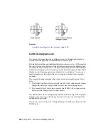
The user coordinate system icon (UCS icon) helps you visualize the current
orientation of the UCS. Several versions of this icon are available, and you
can change its size, location, and color.
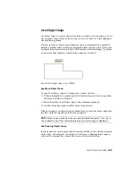
To indicate the location and orientation of the UCS, the UCS icon is displayed
either at the UCS origin point or in the lower-left corner of the current
viewport.
You can choose a 2D or 3D style of the icon to represent the UCS when
working in 2D environment. Shaded style of icon is displayed to represent
the UCS in the 3D environment.
Use the UCSICON command to choose between displaying the 2D or the 3D
UCS icon. The shaded UCS icon is displayed when you open a drawing with
a shaded 3D view that was created in AutoCAD. To indicate the origin and
orientation of the UCS, you can display the UCS icon at the UCS origin point
using the UCSICON command.
The UCS Icon and Multiple Viewports
If you have multiple viewports, each viewport displays its own UCS icon.
132 | Chapter 6 Create and Modify Objects
Содержание 057B1-41A111-1001 - AutoCAD LT 2010
Страница 1: ...AutoCAD LT 2013 User s Guide January 2012 ...
Страница 20: ...zoom 553 xx Contents ...
Страница 26: ...6 ...
Страница 56: ...36 ...
Страница 118: ...98 ...
Страница 288: ...268 ...
Страница 534: ...514 ...
Страница 540: ...520 ...
Страница 574: ...554 ...


