Name
Range
Step
Default
Description
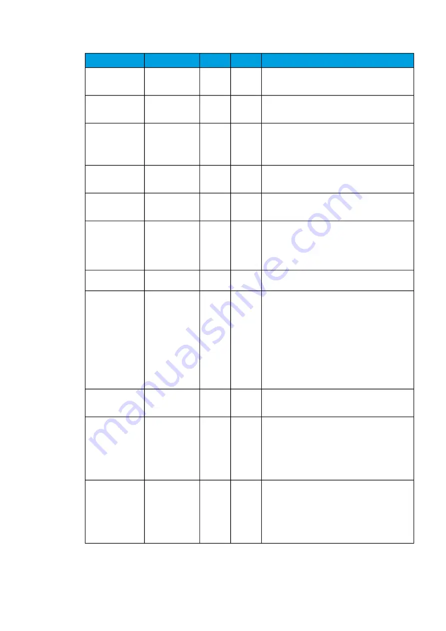
Frequency derivative
defining disturbed
mode
0.000…25.000Hz/
s
0.001Hz/
s
2.100Hz/
s
Defines the speed of the change in frequency; used
to detect the disturbed mode.
Hysteresis setting
for MVAR and PF
control loop
0.000…0.100p.u.
0.001p.u. 0.010p.u. Defines the hysteresis for MVar and PF control.
Maximum time for
setting of Mvar
when
MVarSettingEnableis
true
0.000…1800.000s 0.005s
60.000s
Defines the maximum time for unloading the reactive
power (Q). It also defines the maximum time limit for
changing the reactive power to the reference value. If it is
not reached by this time has passed, the control mode
MVar goes off.
Rate of excitation
rise 0…80 % on
starting
0.000…25.000
0.001
0.200
Defines the rate of excitation rise from 0 % to 80 % from
the reference value, during excitation starting.
Rate of excitation
rise 80…100 % on
starting
0.000…25.000
0.001
0.050
Defines the rate of excitation rise from 80 % to 100 %
from the reference value, during excitation starting.
Start level of
excitation rise on
starting
0.000…25.000p.u. 0.001p.u. 0.000p.u.
Defines the start level of excitation (in per-unit value),
during excitation starting. This parameter is used in
conjunction with field flashing.
See also the parameter "Field flashing" at
Excitation
→
Excitation
→
Power circuit parameters.
Field forcing voltage
factor (neg.value)
-1.0…1.0
0.01
-0.6
Defines the control signal's zero point.
Force PWM control
signal
0: Disabled
1: Forced value
2: Open loop
reference
-
0:
Disabled
Enables and disables the forcing of PWM control signal
values.
If enabled, there are two ways to adjust the values.
The "Open loop reference" option refers to adjustment
done with the "Test mode increase" and "Test mode
decrease" commands. See these parameters at
Excitation
→
I/O
→
DI inputs to excitation.
The "Forced value" option refers to adjustment done with
the "Force PWM control signal value" parameter. See the
"Force PWM control signal value" parameter below.
Force PWM control
signal value
0.000…1.000
0.001
0.000
Defines the forced value, when the "Forced value" option
is selected for the "Force PWM control signal" parameter
above.
AVR reference follow
filter T constant
0.005…50.000s
0.005s
0.010s
Defines the time that precedes the mode change when
the control mode is changed to AVR. The follow filter
reference is based on this value.
For example, if the mode change takes place at
13:01:22.456 and this parameter has been set to "1.000
s", the follow filter reference is fetched from
13:01:21.456.
FCR reference follow
filter T constant
0.005…50.000s
0.005s
0.010s
Defines the time that precedes the mode change when
the control mode is changed to FCR. The follow filter
reference is based on this value.
For example, if the mode change takes place at
13:01:22.456 and this parameter has been set to "1.000
s", the follow filter reference is fetched from
13:01:21.456.
Genera
Generattor Commander
or Commander
Instruction manual
Version: 2.07
460
© Arcteq Relays Ltd
IM00001
Содержание Generator Commander
Страница 1: ...Generator Commander Instruction manual...
Страница 2: ......


