•
CASE 2): if this status is displayed only with control activated, it means that at that moment
a voltage below 1V, instead of battery, is being detected at PIN 20 of the instrument panel;
disconnect the gearshift control connector and read voltage at PIN 20 of the instrument
panel: if voltage is below 1 V, it means that on the brown cable there is a short circuit to
ground; if voltage is above 1 V (approximately battery voltage), replace the "+" button sensor.
Indication on diagnostic tool "Invalid data due to open circuit error";
•
CASE 1): if this status is displayed only with control not activated, it means that circuit from
PIN 20 to PIN 34 of the instrument panel is interrupted or that PIN 34 is not grounded: check
the instrument panel connector and the "+" button connector: if they are not OK, restore; if
they are OK, check continuity on the brown cable: if it is not OK, restore; if it is OK, check
continuity on the black cable from the "+" button connector to PIN 34 of the instrument panel:
if it is not OK, restore; if it is OK, check continuity of the "+" button from the "+" button
connector (between black cable and green cable): if it is not OK, change the control; if it is
OK, check, with key to ON, that the black cable is not grounded and then change the in-
strument panel.
•
CASE 2): if this status is displayed only with control activated, it means that circuit from PIN
19 to PIN 34 of the instrument panel is interrupted: check the instrument panel connector
and the "+" button connector: if they are not OK, restore; if they are OK, check continuity on
the white cable: if it is not OK, restore; if it is OK, check, with control activated, that there is
no continuity of the "+" button from the "+" button connector (between the black cable and
the yellow cable) and then replace the control.
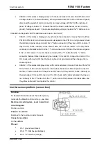
Inertial sensor platform (sensor box)
Function:
To transmit information about the motorcycle dy-
namics to the Marelli control unit (e.g.: yaw rate).
Electrical circuit diagram - Level in electrical
circuit diagram:
Traction control.
Position on vehicle:
Fastened to the fuel tank, under the seat.
Connector position:
On the platform
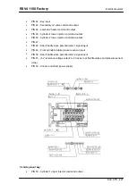
Pin-out:
•
Pin 1: ground lead (black)
•
Pin 2: "L" CAN line (white/black)
•
Pin 3: "H" CAN line (orange)
Electrical system
RSV4 1100 Factory
ELE SYS - 222
Содержание RSV4 1100 Factory
Страница 1: ...SERVICE STATION MANUAL 2Q000401 RSV4 1100 Factory ...
Страница 4: ......
Страница 6: ...INDEX OF TOPICS CHARACTERISTICS CHAR ...
Страница 55: ...INDEX OF TOPICS SPECIAL TOOLS S TOOLS ...
Страница 63: ...INDEX OF TOPICS MAINTENANCE MAIN ...
Страница 89: ...INDEX OF TOPICS ELECTRICAL SYSTEM ELE SYS ...
Страница 245: ...INDEX OF TOPICS ENGINE FROM VEHICLE ENG VE ...
Страница 270: ...INDEX OF TOPICS ENGINE ENG ...
Страница 384: ...INDEX OF TOPICS POWER SUPPLY P SUPP ...
Страница 387: ... Remove the fuel pump Injection RSV4 1100 Factory Power supply P SUPP 387 ...
Страница 393: ...INDEX OF TOPICS SUSPENSIONS SUSP ...
Страница 417: ...INDEX OF TOPICS CHASSIS CHAS ...
Страница 455: ...INDEX OF TOPICS BRAKING SYSTEM BRAK SYS ...
Страница 457: ...Operating diagram ABS functional diagram key RSV4 1100 Factory Braking system BRAK SYS 457 ...
Страница 488: ...INDEX OF TOPICS COOLING SYSTEM COOL SYS ...
Страница 499: ...INDEX OF TOPICS BODYWORK BODYW ...
Страница 540: ...INDEX OF TOPICS PRE DELIVERY PRE DE ...
Страница 546: ... Fit the two seater saddle Pre delivery RSV4 1100 Factory PRE DE 546 ...


