7
- 83
3$57(&,&/2
&+$66,63$576
7.8.4 DESMONTAJE BARRA - BOTELLA
Lea con cuidado 1.2.3 (ACEITE PARA HORQUILLA),
1.4 (PRECAUCIONES E INFORMACIONES GENERA-
LES) y 2.25 (FRONT FORK).
La barra portarueda derecha e izquierda tie-
nen los mismos componentes en el interior.
Por lo tanto, las operaciones son válidas para ambos.
X
Desmonte el grupo barra-botella, véase 7.8.3 (DES-
MONTAJE GRUPO BARRA-BOTELLA (CON HOR-
QUILLA INSTALADA)) (con horquilla instalada).
Peligro de salida aceite.
El grupo barra-botella está lleno de aceite.
Al extraerlo no lo revolque ni lo incline excesi-
vamente.
X
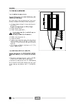
Destornille y quite el tapón (1) y guarde la junta tórica
(2).
X
Extraiga según el siguiente orden:
- anillo portaresorte (4);
- tubo de precarga (5);
- tubo de guía del resorte (6).
X
Prepare un recipiente graduado con capacidad míni-
ma de 450 cm
!
.
X
Introduzca del todo la barra en la botella, revolque el
grupo barra-botella y descargue el aceite en el reci-
piente.
X
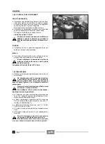
Destornille y quite el tornillo (7) y guarde la arandela
de retención (8).
Para destornillar el tornillo (7) es aconsejable
utilizar una pistola atornilladora de aire para
dar un golpe seco y permitir así el desbloqueo, elimi-
nando el efecto del LOCTITE
®
270.
Durante el reensamblaje aplique sobre la ros-
ca del tornillo (7) LOCTITE
®
270.
Par de apriete tornillo (7): 50 Nm (5 kgm)
X
Quite según el orden la barra portarueda (9) y el resor-
te (10).
X
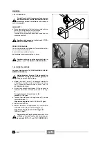
Extraiga según el orden:
- junta rascapolvo (11);
- anillo Seeger (12);
Durante el reensamblaje coloque el anillo
Seeger (12) con la arista viva contra el alo-
jamiento de la horquilla (véase figura).
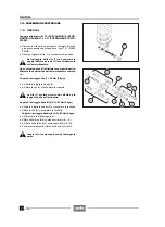
- retén (13);
- casquillo de guía (14);
- casquillo de deslizamiento (15);
- distanciador (16);
- otro casquillo de deslizamiento (15).
Lave todos los componentes con detergente
limpio.
7.8.4 DISASSEMBLING THE WHEEL-HOLDER
TUBE/SLIDER UNIT
Read 1.2.3 (FORK OIL), 1.4 (PRECAUTIONS AND
GENERAL INFORMATION) and 2.25 (FRONT FORK)
carefully.
The right and left fork tubes have the same in-
ner components. The operations described
below are therefore valid for both tubes.
X
Remove the wheel-holder tube/slider unit, see 7.8.3
(REMOVING THE WHEEL-HOLDER TUBE/SLIDER
UNIT (WITH INSTALLED FORK)).
Warning! The oil may flow out.
The wheel-holder tube/slider unit is full of oil.
Neither overturn it, nor incline it excessively
during the removal.
X
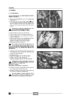
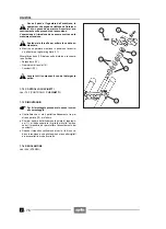
Unscrew and remove the plug (1) and take the O-ring
(2).
X
Withdraw the following parts in the given order:
- spring holder ring (4);
- preload tube (5);
- spring guide tube (6).
X
Prepare a graduated container with at least 450 cm
!
capacity.
X
Make the tube get into the slider completely, overturn
the tube/slider unit and drain the oil in the container.
X
Unscrew and remove the screw (7) and take the seal-
ing washer (8).
To unscrew the screw (7), it is advisable to
use a percussion screwdriver, thanks to
which it will be possible to detach the screw from the
LOCTITE
®
270.
Upon reassembly, apply LOCTITE
®
270 on the
thread of the screw (7).
Screw (7) driving torque: 50 Nm (5 kgm).
X
Withdraw first the wheel-holder tube (9) and then the
spring (10).
X
Remove the following parts in the given order:
- antidust gasket (11);
- retaining ring (seeger) (12);
Upon reassembly, position the retaining
ring (seeger) (12) with its sharp edge rest-
ing on the adjacent elements (see figure).
- seal (13);
- guide bush (14);
- slide bush (15);
- spacer (16);
- the other slide bush (15).
Wash all the components with a clean deter-
gent.
Содержание Pegaso 650
Страница 1: ......
Страница 3: ...0 4 NOTE NOTES ANMERKUNGEN ...
Страница 4: ...1 1 1 2 3 4 5 6 7 8 INFORMAZIONI GENERALI INFORMACIONES GENERALES GENERAL INFORMATION ...
Страница 42: ......
Страница 69: ...3 1 1 2 3 4 5 6 7 8 MOTORE MOTOR ENGINE ...
Страница 90: ...3 22 MOTORE NOTE NOTAS NOTES ...
Страница 91: ...4 1 1 2 3 4 5 SISTEMA DI ALIMENTAZIONE SISTEMA DE ALIMENTACIÓN FUEL SYSTEM ...
Страница 116: ...4 26 SISTEMA DI ALIMENTAZIONE NOTE NOTAS NOTES ...
Страница 117: ...5 1 1 2 3 4 5 6 7 8 IMPIANTO DI RAFFREDDAMENTO SISTEMA DE REFRIGERACIÓN COOLING SYSTEM ...
Страница 130: ...5 14 IMPIANTO DI RAFFREDDAMENTO SISTEMA DE REFRIGERACIÓN COOLING SYSTEM NOTE NOTAS NOTES ...
Страница 131: ...6 1 6 1 2 3 4 5 6 7 8 IMPIANTO ELETTRICO INSTALACIÓN ELÉCTRICA ELECTRICAL SYSTEM ...
Страница 176: ...IMPIANTO ELETTRICO INSTALACIÓN ELÉCTRICA ELECTRICAL SYSTEM 6 46 NOTE NOTAS NOTES ...
Страница 177: ...7 1 1 2 3 4 5 6 7 8 CICLISTICA PARTE CICLO CHASSIS PARTS ...
Страница 226: ... 67 3 57 2 66 6 3 576 7 50 5827 3267 5 25 58 75 6 5 5 5 ...
Страница 242: ... 67 3 57 2 66 6 3 576 7 66 5 12 17 5 25 5 12 17 52 5217 5 ...
Страница 246: ... 67 3 57 2 66 6 3 576 7 70 5 12 3267 5 25 5 12 75 6 52 5 5 5 ...
Страница 272: ... 67 3 57 2 66 6 3 576 7 96 NOTE NOTAS NOTES ...
Страница 273: ...8 1 1 2 3 4 5 6 7 8 INFORMAZIONI PER LE RIPARAZIONI INFORMACIONES PARA LAS REPARACIONES REPAIRS ...
Страница 301: ...INFORMAZIONI PER LE RIPARAZIONI INFORMACIONES PARA LAS REPARACIONES REPAIRS 8 29 E F E F G H G H ...
Страница 302: ...INFORMAZIONI PER LE RIPARAZIONI INFORMACIONES PARA LAS REPARACIONES REPAIRS 8 30 I L I M L N M N ...
Страница 303: ...INFORMAZIONI PER LE RIPARAZIONI INFORMACIONES PARA LAS REPARACIONES REPAIRS 8 31 O P Q P O R Q R ...
Страница 310: ...INFORMAZIONI PER LE RIPARAZIONI INFORMACIONES PARA LAS REPARACIONES REPAIRS 8 38 NOTE NOTAS NOTES ...
Страница 311: ...INFORMAZIONI PER LE RIPARAZIONI INFORMACIONES PARA LAS REPARACIONES REPAIRS 8 39 ...


