3
- 21
MOTOR
ENGINE
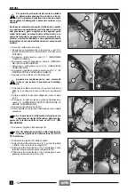
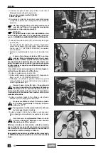
In the first phase, the pin (5), the adjusting
bush (6) and the lock ring (7) must be screwed
by hand.
◆
Introduce and screw the pin (5) that fastens frame,en-
gine and rear fork, holding the adjusting bush (6) and
using the apposite socket spanner, see 1.8 (SPECIAL
TOOLS).
◆
Screw the adjusting bush (6) until it reaches the end of
stroke, then give it another one fourth turn.
Tightening of the adjusting bush (6):
c one fourth turn.
◆
Hold the adjusting bush (6) and tighten the fork pin (5).
Pin (5) driving torque: 100 Nm (10 kgm).
◆
Put back the washer.
◆
Hold the adjusting bush (6) and at the same time
screw the lock ring (7).
Lock ring (7) driving torque:
40 Nm (4 kgm).
From this point onwards, proceed with the re-
installation of the engine on the frame starting
from NOTE (X), see 3.2 (REMOVING THE EN-
GINE FROM THE FRAME) and following the reverse
order with respect to the removal.
◆
Top up the expansion tank, see 2.14 (CHECKING
AND TOPPING UP COOLANT).
◆
Top up the engine oil tank, see 2.12 (CHECKING THE
ENGINE OIL LEVEL AND TOPPING UP).
◆
If the engine has been overhauled, bleed the oil deliv-
ery pump, see 2.13.1 (AIR BLEEDING FROM OIL
DELIVERY PUMP).
◆
Check the gearing chain tension and if necessary ad-
just it, see 2.16.1 (CLEARANCE CONTROL) and
2.16.3 (ADJUSTMENT).
Carry out a general check of all the compo-
nents involved in the operations mentioned
above, and in particular check the following:
◆
Correct fastening of the electric cables.
◆
Correct introduction of pipes and couplings.
Cables, pipes, couplings must be neither
twisted nor crushed.
◆
Clutch, accelerator, cold start cables must all move
freely and must not stretch excessively when the han-
dlebar is rotated.
◆
Correct positioning of the gearshift foot lever.
◆
Correct oil and coolant level.
◆
Correct driving torque of the engine fastening
screws/nuts.
a
a
a
a
Durante la primera fase, el eje (5), la tuerca de
regulación (6) y la tuerca de bloqueo (7), de-
ben ser enroscados manualmente.
◆
Introduzca y enrosque el eje (5) de fijación basti-
dor/motor/basculante, manteniendo bloqueada la tuer-
ca de regulación (6) utilizando la correspondiente llave
tubular, véase 1.8 (EQUIPOS ESPECIALES).
◆
Enrosque la tuerca de regulación (6) hasta llegar al to-
pe, siga enroscándola hasta 1/4 de vuelta.
Apriete tuerca de regulación (6):
co 1/4 de vuelta.
◆
Manteniendo bloqueada la tuerca de regulación (6),
apriete el eje basculante (5).
Par de apriete eje (5): 100 Nm (10 kgm).
◆
Vuelva a colocar la arandela.
◆
Mantenga bloqueada la arandela de regulación (6) y, a
la vez, enrosque la tuerca de bloqueo (7).
Par de apriete tuerca de bloqueo (7):
40 Nm (4 kgm).
A partir de este punto, siga adelante con la
instalación del motor sobre el bastidor de ma-
nera opuesta al desmontaje, empezando por
la NOTA (X), véase 3.2 (EXTRACCION DEL MOTOR
DEL BASTIDOR).
◆
Efectúe el relleno del líquido refrigerante, véase
2.14 (CONTROL Y RELLENO DEL LÍQUIDO REFRI-
GERANTE).
◆
Efectúe el relleno aceite motor, véase 2.12 (CON-
TROL DEL NIVEL DEL ACEITE DEL MOTOR Y RE-
LLENO).
◆
En caso de que el motor haya sido revisado, efectúe la
purga aire bomba de alimentación aceite, véase
2.13.1 (PURGA DEL AIRE DE LA BOMBA DE ALI-
MENTACIÓN DEL ACEITE).
◆
Controle la tensión de la cadena de transmisión y si
acaso ajústela, véanse 2.16.1 (CONTROL DEL JUE-
GO) y 2.16.3 (AJUSTE).
Efectúe un control general en todos los com-
ponentes sobre los que se ha trabajado y en
particular:
◆
Correcta fijación cables eléctricos.
◆
Correcta introducción tubos y manguitos.
No deben estar retorcidos y/o aplastados.
◆
Cables embrague, acelerador, arranque en frío deben
deslizarse libremente y no deben tensarse cuando se
gira el manillar.
◆
Correcta colocación pedal mando cambio.
◆
Nivel correcto del aceite y del líquido refrigerante.
◆
Correcto par de apriete tornillos/tuercas fijación motor.
a
a
a
a
Содержание Pegaso 650
Страница 1: ......
Страница 3: ...0 4 NOTE NOTES ANMERKUNGEN ...
Страница 4: ...1 1 1 2 3 4 5 6 7 8 INFORMAZIONI GENERALI INFORMACIONES GENERALES GENERAL INFORMATION ...
Страница 42: ......
Страница 69: ...3 1 1 2 3 4 5 6 7 8 MOTORE MOTOR ENGINE ...
Страница 90: ...3 22 MOTORE NOTE NOTAS NOTES ...
Страница 91: ...4 1 1 2 3 4 5 SISTEMA DI ALIMENTAZIONE SISTEMA DE ALIMENTACIÓN FUEL SYSTEM ...
Страница 116: ...4 26 SISTEMA DI ALIMENTAZIONE NOTE NOTAS NOTES ...
Страница 117: ...5 1 1 2 3 4 5 6 7 8 IMPIANTO DI RAFFREDDAMENTO SISTEMA DE REFRIGERACIÓN COOLING SYSTEM ...
Страница 130: ...5 14 IMPIANTO DI RAFFREDDAMENTO SISTEMA DE REFRIGERACIÓN COOLING SYSTEM NOTE NOTAS NOTES ...
Страница 131: ...6 1 6 1 2 3 4 5 6 7 8 IMPIANTO ELETTRICO INSTALACIÓN ELÉCTRICA ELECTRICAL SYSTEM ...
Страница 176: ...IMPIANTO ELETTRICO INSTALACIÓN ELÉCTRICA ELECTRICAL SYSTEM 6 46 NOTE NOTAS NOTES ...
Страница 177: ...7 1 1 2 3 4 5 6 7 8 CICLISTICA PARTE CICLO CHASSIS PARTS ...
Страница 226: ... 67 3 57 2 66 6 3 576 7 50 5827 3267 5 25 58 75 6 5 5 5 ...
Страница 242: ... 67 3 57 2 66 6 3 576 7 66 5 12 17 5 25 5 12 17 52 5217 5 ...
Страница 246: ... 67 3 57 2 66 6 3 576 7 70 5 12 3267 5 25 5 12 75 6 52 5 5 5 ...
Страница 272: ... 67 3 57 2 66 6 3 576 7 96 NOTE NOTAS NOTES ...
Страница 273: ...8 1 1 2 3 4 5 6 7 8 INFORMAZIONI PER LE RIPARAZIONI INFORMACIONES PARA LAS REPARACIONES REPAIRS ...
Страница 301: ...INFORMAZIONI PER LE RIPARAZIONI INFORMACIONES PARA LAS REPARACIONES REPAIRS 8 29 E F E F G H G H ...
Страница 302: ...INFORMAZIONI PER LE RIPARAZIONI INFORMACIONES PARA LAS REPARACIONES REPAIRS 8 30 I L I M L N M N ...
Страница 303: ...INFORMAZIONI PER LE RIPARAZIONI INFORMACIONES PARA LAS REPARACIONES REPAIRS 8 31 O P Q P O R Q R ...
Страница 310: ...INFORMAZIONI PER LE RIPARAZIONI INFORMACIONES PARA LAS REPARACIONES REPAIRS 8 38 NOTE NOTAS NOTES ...
Страница 311: ...INFORMAZIONI PER LE RIPARAZIONI INFORMACIONES PARA LAS REPARACIONES REPAIRS 8 39 ...


