7
- 73
3$57(&,&/2
&+$66,63$576
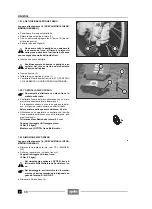
7.6.1 SUSTITUCION PASTILLAS FRENO
Lea con mucho cuidado 1.4 (PRECAUCIONES E IN-
FORMACIONES GENERALES).
X
Coloque el vehículo sobre el caballete.
X
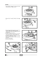
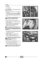
Destornille y quite los dos tornillos (1) que sujetan la
pinza (2) a la placa de soporte (3).
X
Extraiga la pinza del disco y desplácela hacia un lado.
El tubo del líquido de frenos puede dejarse
conectado.
X
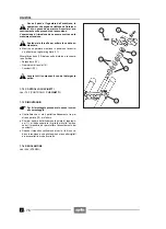
Apriete, como indicado en la figura, desplazando uni-
formemente el flotador (4) hacia el pistón.
X
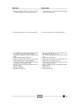
Extraiga las dos pastillas (primero la interior).
Tras haber quitado las pastillas no accione la
palanca de mando del freno, en caso contrario
los pistones de la pinza podrían salirse del
alojamiento y provocar la pérdida del líquido de fre-
nos.
X
Introduzca dos pastillas nuevas.
Sustituya siempre ambas pastillas y controle
que estén bien colocadas en el interior de la
pinza.
Límite de desgaste de las pastillas: 1 mm
X
Introduzca la pinza (2) en el disco y colóquela en la
placa de soporte (3).
X
Atornille los dos tornillos de sujeción (1).
Par de apriete tornillos (1): 25 Nm (2,5 kgm)
X
Controle el nivel líquido frenos, véase 2.18 (CON-
TROL Y RELLENO LIQUIDO FRENO TRASERO).
7.6.2 CONTROL DISCO FRENO
Véase 7.5.2 (CONTROL DISCO FRENO).
Valor mínimo del espesor del disco : 4,5 mm
Tolerancia de oscilación del disco: 0,3 mm
7.6.3 DESMONTAJE DISCO FRENO
Lea con cuidado 1.4 (PRECAUCIONES E INFORMA-
CIONES GENERALES).
X
Extraiga la rueda trasera, véase 7.3.1 (DESMONTA-
JE).
X
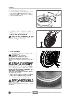
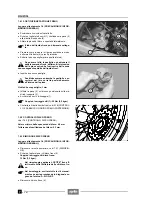
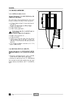
Destornille y quite los seis tornillos disco freno (5).
Par de apriete tornillos disco freno:
12 Nm (1,2 kgm).
Durante el reensamblaje aplique LOCTITE
®
frena roscas medio sobre la rosca de los tor-
nillos disco freno.
Durante el reensamblaje atornille todos los
tornillos manualmente y apriételos actuando
en diagonal según el siguiente orden: A-B-C-D-E-F
X
Extraiga el disco freno (6).
7.6.1 CHANGING THE BRAKE PADS
Read 1.4 (PRECAUTIONS AND GENERAL INFORMA-
TION) carefully.
X
Position the vehicle on the stand.
X
Unscrew and remove the two screws (1) that fasten
the caliper (2) to the support plate (3).
X
Withdraw the caliper from the disc and mode it side-
wards.
It is not necessary to disconnect the brake flu-
id pipe.
X
Press, as indicated in the figure, moving the float (4)
uniformly towards the caliper pin.
X
Extract the two pads (the inner one first).
After removing the pads, do not pull the brake
control lever, otherwise the caliper pin may go
out of its seat and cause the outflow of the
brake fluid.
X
Insert two new pads.
Always change both pads and make sure that
they are correctly positioned inside the cali-
per.
Pad wear limit: 1 mm.
X
Insert the caliper (2) on the disc and position it on the
support plate (3).
X
Tighten the two fastening screws (1).
Screw (1) driving torque: 25 Nm (2.5 kgm).
X
Check the brake fluid level, see 2.18 (CHECKING
AND TOPPING UP THE REAR BRAKE FLUID).
7.6.2 CHECKING THE BRAKE DISC
See 7.5.2 (CHECKING THE BRAKE DISC).
Brake disc min. thickness: 4.5 mm.
Brake disc max. wobbling: 0.3 mm
7.6.3 REMOVING THE BRAKE DISC
Read 1.4 (PRECAUTIONS AND GENERAL INFORMA-
TION) carefully.
X
Remove the rear wheel, see 7.3.1 (DISASSEMBLY).
X
Unscrew and remove the six brake disc screws (5).
Brake disc screw driving torque:
12 Nm (1.2 kgm).
Upon reassembly, apply medium LOCTITE
®
thread restrainer on the thread of the brake
disc screws.
Upon reassembly, screw all the screws manu-
ally and tighten them proceeding diagonally in
the following order: A-B-C-D-E-F.
X
Remove the brake disc (6).
Содержание Pegaso 650
Страница 1: ......
Страница 3: ...0 4 NOTE NOTES ANMERKUNGEN ...
Страница 4: ...1 1 1 2 3 4 5 6 7 8 INFORMAZIONI GENERALI INFORMACIONES GENERALES GENERAL INFORMATION ...
Страница 42: ......
Страница 69: ...3 1 1 2 3 4 5 6 7 8 MOTORE MOTOR ENGINE ...
Страница 90: ...3 22 MOTORE NOTE NOTAS NOTES ...
Страница 91: ...4 1 1 2 3 4 5 SISTEMA DI ALIMENTAZIONE SISTEMA DE ALIMENTACIÓN FUEL SYSTEM ...
Страница 116: ...4 26 SISTEMA DI ALIMENTAZIONE NOTE NOTAS NOTES ...
Страница 117: ...5 1 1 2 3 4 5 6 7 8 IMPIANTO DI RAFFREDDAMENTO SISTEMA DE REFRIGERACIÓN COOLING SYSTEM ...
Страница 130: ...5 14 IMPIANTO DI RAFFREDDAMENTO SISTEMA DE REFRIGERACIÓN COOLING SYSTEM NOTE NOTAS NOTES ...
Страница 131: ...6 1 6 1 2 3 4 5 6 7 8 IMPIANTO ELETTRICO INSTALACIÓN ELÉCTRICA ELECTRICAL SYSTEM ...
Страница 176: ...IMPIANTO ELETTRICO INSTALACIÓN ELÉCTRICA ELECTRICAL SYSTEM 6 46 NOTE NOTAS NOTES ...
Страница 177: ...7 1 1 2 3 4 5 6 7 8 CICLISTICA PARTE CICLO CHASSIS PARTS ...
Страница 226: ... 67 3 57 2 66 6 3 576 7 50 5827 3267 5 25 58 75 6 5 5 5 ...
Страница 242: ... 67 3 57 2 66 6 3 576 7 66 5 12 17 5 25 5 12 17 52 5217 5 ...
Страница 246: ... 67 3 57 2 66 6 3 576 7 70 5 12 3267 5 25 5 12 75 6 52 5 5 5 ...
Страница 272: ... 67 3 57 2 66 6 3 576 7 96 NOTE NOTAS NOTES ...
Страница 273: ...8 1 1 2 3 4 5 6 7 8 INFORMAZIONI PER LE RIPARAZIONI INFORMACIONES PARA LAS REPARACIONES REPAIRS ...
Страница 301: ...INFORMAZIONI PER LE RIPARAZIONI INFORMACIONES PARA LAS REPARACIONES REPAIRS 8 29 E F E F G H G H ...
Страница 302: ...INFORMAZIONI PER LE RIPARAZIONI INFORMACIONES PARA LAS REPARACIONES REPAIRS 8 30 I L I M L N M N ...
Страница 303: ...INFORMAZIONI PER LE RIPARAZIONI INFORMACIONES PARA LAS REPARACIONES REPAIRS 8 31 O P Q P O R Q R ...
Страница 310: ...INFORMAZIONI PER LE RIPARAZIONI INFORMACIONES PARA LAS REPARACIONES REPAIRS 8 38 NOTE NOTAS NOTES ...
Страница 311: ...INFORMAZIONI PER LE RIPARAZIONI INFORMACIONES PARA LAS REPARACIONES REPAIRS 8 39 ...


