6
- 7
INSTALACIÓN ELÉCTRICA
ELECTRICAL SYSTEM
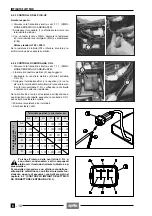
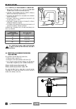
6.1.3 CONTROL DE LA CONTINUIDAD DEL
ALTERNADOR
Con el motor apagado:
◆
Quite el panel izquierdo, véase 7.1.4 (DESMONTAJE
PANELES LATERALES DERECHO E IZQUIERDO).
◆
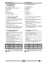
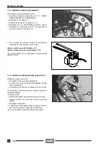
Desconecte el conector de los cables del alternador (1).
◆
Con un tester compruebe la continuidad entre los ca-
bles del estator (en los terminales hembra interiores,
cables amarillos (G)). También, compruebe el aisla-
miento del soporte del estator.
Valor estándar de la resistencia: 0,1 - 1
Ω
Valor estándar de la resistencia entre cables y sopor-
te estator:
∞
(infinito)
6.1.4 CONTROL DEL REGULADOR DE TENSIÓN
◆
Quite el sillín, véase 7.1.3 (DESMONTAJE SILLIN).
◆
Desconecte los conectores (2-3).
◆
Destornille y extraiga el tornillo (4) y desconecte el ter-
minal del cable (5) y del cable (6) (cables de masa).
Cuando reinstale, conecte nuevamente am-
bos cables (5) y (6).
◆
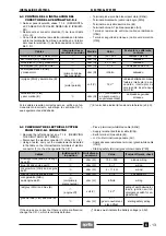
Con un tester (escala x 1 k
Ω
), mida del lado del regu-
lador (terminales machos interiores), la resistencia en-
tre los cables indicados en la tabla indicada a conti-
nuación.
Si la resistencia medida es incorrecta, substituya el re-
gulador
Este método de medición es aproximado; si
es posible, controle el funcionamiento correc-
to de la recarga utilizando otro regulador que
esté seguro que funcione.
Terminal positivo (+) del tester sobre:
G
G
G
V
R/Bi
M
Terminal negativo (–)
del tester sobre:
G
∞
∞
1 -
∞ ∞
1 -
∞
G
∞
∞
1 -
∞ ∞
1 -
∞
G
∞
∞
1 -
∞ ∞
1 -
∞
V
∞
∞
∞
∞
1 -
∞
R/Bi
1 -
∞
1 -
∞
1 -
∞
2 -
∞
2 -
∞
M
∞
∞
∞
1 -
∞
1 -
∞
a
a
6.1.3 CHECKING THE ALTERNATOR
CONTINUITY
With the engine switched off:
◆
Remove left side panel, see 7.1.4 (REMOVING THE
RIGHT AND LEFT SIDES).
◆
Disconnect the alternator cable connector (1).
◆
Using a pocket tester, check the voltage continuity
between the cables of the stator (on the internal fema-
le terminals, yellow cables (G)).
Also check the insulation of the stator support.
Standard resistance value: 0,1 - 1
Ω
Standard value of resistance between stator cables
and support:
∞
(infinite)
6.1.4 CHECKING THE VOLTAGE REGULATOR
◆
Remove saddle, see 7.1.3 (REMOVING THE SADD-
LE).
◆
Disconnect the connectors (2-3),
◆
Unscrew and remove screw (4) and disconnect the ter-
minal of cable (5) and cable (6) (earth cables).
On reassembly, re-connect both cables (5)
and (6).
◆
Using a pocket tester (scale x 1 k
Ω
), measure from the
regulator side (internal male terminals) the resistance
between the cables indicated in the table below.
If the resistance measured is not correct, replace the
regulator.
This measuring method is approximate; if
possible check the correct operation of the re-
charging system using another regulator in
perfect condition.
Positive terminal (+) of the tester on:
G
G
G
V
R/Bi
M
Negative terminal (–)
of the tester on:
G
∞
∞
1 -
∞ ∞
1 -
∞
G
∞
∞
1 -
∞ ∞
1 -
∞
G
∞
∞
1 -
∞ ∞
1 -
∞
V
∞
∞
∞
∞
1 -
∞
R/Bi
1 -
∞
1 -
∞
1 -
∞
2 -
∞
2 -
∞
M
∞
∞
∞
1 -
∞
1 -
∞
a
a
Содержание Pegaso 650
Страница 1: ......
Страница 3: ...0 4 NOTE NOTES ANMERKUNGEN ...
Страница 4: ...1 1 1 2 3 4 5 6 7 8 INFORMAZIONI GENERALI INFORMACIONES GENERALES GENERAL INFORMATION ...
Страница 42: ......
Страница 69: ...3 1 1 2 3 4 5 6 7 8 MOTORE MOTOR ENGINE ...
Страница 90: ...3 22 MOTORE NOTE NOTAS NOTES ...
Страница 91: ...4 1 1 2 3 4 5 SISTEMA DI ALIMENTAZIONE SISTEMA DE ALIMENTACIÓN FUEL SYSTEM ...
Страница 116: ...4 26 SISTEMA DI ALIMENTAZIONE NOTE NOTAS NOTES ...
Страница 117: ...5 1 1 2 3 4 5 6 7 8 IMPIANTO DI RAFFREDDAMENTO SISTEMA DE REFRIGERACIÓN COOLING SYSTEM ...
Страница 130: ...5 14 IMPIANTO DI RAFFREDDAMENTO SISTEMA DE REFRIGERACIÓN COOLING SYSTEM NOTE NOTAS NOTES ...
Страница 131: ...6 1 6 1 2 3 4 5 6 7 8 IMPIANTO ELETTRICO INSTALACIÓN ELÉCTRICA ELECTRICAL SYSTEM ...
Страница 176: ...IMPIANTO ELETTRICO INSTALACIÓN ELÉCTRICA ELECTRICAL SYSTEM 6 46 NOTE NOTAS NOTES ...
Страница 177: ...7 1 1 2 3 4 5 6 7 8 CICLISTICA PARTE CICLO CHASSIS PARTS ...
Страница 226: ... 67 3 57 2 66 6 3 576 7 50 5827 3267 5 25 58 75 6 5 5 5 ...
Страница 242: ... 67 3 57 2 66 6 3 576 7 66 5 12 17 5 25 5 12 17 52 5217 5 ...
Страница 246: ... 67 3 57 2 66 6 3 576 7 70 5 12 3267 5 25 5 12 75 6 52 5 5 5 ...
Страница 272: ... 67 3 57 2 66 6 3 576 7 96 NOTE NOTAS NOTES ...
Страница 273: ...8 1 1 2 3 4 5 6 7 8 INFORMAZIONI PER LE RIPARAZIONI INFORMACIONES PARA LAS REPARACIONES REPAIRS ...
Страница 301: ...INFORMAZIONI PER LE RIPARAZIONI INFORMACIONES PARA LAS REPARACIONES REPAIRS 8 29 E F E F G H G H ...
Страница 302: ...INFORMAZIONI PER LE RIPARAZIONI INFORMACIONES PARA LAS REPARACIONES REPAIRS 8 30 I L I M L N M N ...
Страница 303: ...INFORMAZIONI PER LE RIPARAZIONI INFORMACIONES PARA LAS REPARACIONES REPAIRS 8 31 O P Q P O R Q R ...
Страница 310: ...INFORMAZIONI PER LE RIPARAZIONI INFORMACIONES PARA LAS REPARACIONES REPAIRS 8 38 NOTE NOTAS NOTES ...
Страница 311: ...INFORMAZIONI PER LE RIPARAZIONI INFORMACIONES PARA LAS REPARACIONES REPAIRS 8 39 ...

