7
- 11
3$57(&,&/2
&+$66,63$576
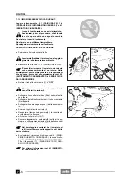
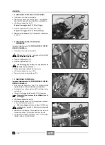
7.1.5 DESMONTAJE PORTAEQUIPAJES TRASERO
X
Coloque el vehículo sobre el caballete.
X
Desmonte los paneles laterales, véase 7.1.4 (DES-
MONTAJE PANELES LATERALES DERECHO E IZ-
QUIERDO).
X
+
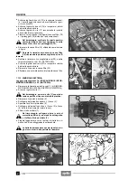
Destornille y quite el tornillo (1).
Par de apriete tornillo (1): 10 Nm (1kgm)
X
Destornille y quite el tornillo (2) y ambos tornillos (3).
Par de apriete (2-3): 8 Nm (0,8 kgm)
X
Quite el portaequipajes (4) y guarde los casquillos y
los elementos de goma.
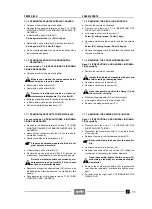
7.1.6 DESMONTAJE GRUPO GUARDABARROS
DELANTERO
Lea con cuidado 1.4 (PRECAUCIONES E INFORMA-
CIONES GENERALES).
X
Coloque el vehículo sobre el caballete.
Maneje con cuidado los componentes barni-
zados para no rayarlo o dañarlos.
X
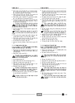
Destornille y quite el tornillo (5).
X
Destornille y quite el tornillo (6).
Durante la instalación vuelva a colocar co-
rrectamente la abrazadera (7) y el collar (8).
X
Extraiga el guardabarros (9) desde la parte delantera.
X
+
Destornille y quite los dos tornillos (10).
X
Quite el soporte del guardabarros (11).
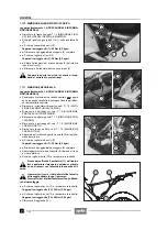
7.1.7 DESMONTAJE SOPORTE PORTAMATRICULA
Lea con cuidado 1.4 (PRECAUCIONES E INFORMA-
CIONES GENERALES).
X
Desmonte los paneles laterales, véase 7.1.4 (DES-
MONTAJE PANELES LATERALES DERECHO E IZ-
QUIERDO).
X
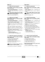
Desconecte el conector eléctrico (12) (en la parte iz-
quierda del vehículo).
X
Suelte los cables de la abrazadera (13).
Prepare otra abrazadera para sustituir a la ori-
ginal durante el montaje.
X
+
Destornille y quite el tornillo (14).
X
Destornille y quite los dos tornillos (15), guarde las
arandelas y, eventualmente, los elementos de goma.
Durante el montaje apriete con cuidado y mo-
deradamente los dos tornillos (15) en cuanto
se fijan en el material plástico.
X
Desmonte el soporte portamatrícula (16) junto con los
indicadores de dirección traseros, luz matrícula y faro
trasero.
X
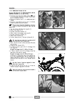
Para desmontar el faro trasero véase 7.1.22 (DES-
MONTAJE FARO TRASERO).
7.1.5 REMOVING THE REAR LUGGAGE RACK
X
Position the vehicle on the stand.
X
Remove the sides, see 7.1.4 (REMOVING THE
RIGHT AND LEFT SIDES).
X
+
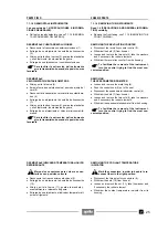
Unscrew and remove the screw (1).
Screw (1) driving torque: 10 Nm (1 kgm).
X
Unscrew and remove the screw (2) and the two screws
(3).
Screw (2-3) driving torque: 8 Nm (0.8 kgm).
X
Remove the luggage rack (4) and take the bushes and
the rubber elements.
7.1.6 REMOVING THE FRONT MUDGUARD UNIT
Read 1.4 (PRECAUTIONS AND GENERAL INFORMA-
TION) carefully.
X
Position the vehicle on the stand.
Handle the painted components with care and
avoid scraping or damaging them.
X
Unscrew and remove the screw (5).
X
Unscrew and remove the screw (6).
Upon reassembly, position the clamp (7) and
the collar (8) correctly.
X
Withdraw the mudguard (9) from the front part.
X
+
Unscrew and remove the two screws (10).
X
Remove the mudguard support (11).
7.1.7 REMOVING THE NUMBER PLATE HOLDER
Read 1.4 (PRECAUTIONS AND GENERAL INFORMA-
TION) carefully.
X
Remove the sides, see 7.1.4 (REMOVING THE
RIGHT AND LEFT SIDES).
X
Disconnect the electric connector (12) (on the left side
of the vehicle).
X
Release the wiring from the fastening clamp (13).
Get another clamp to be used for the reassem-
bly.
X
Unscrew and remove the screw (14).
X
Unscrew and remove the two screws (15), taking the
washers and if necessary the rubber elements.
Upon reassembly, tighten the two screws (15)
moderately, since they are screwed onto plas-
tic material.
X
Remove the number plate holder (16) together with
rear direction indicators, number plate light and rear
light.
X
To remove the rear light, see 7.1.22 (REMOVING THE
REAR LIGHT).
Содержание Pegaso 650
Страница 1: ......
Страница 3: ...0 4 NOTE NOTES ANMERKUNGEN ...
Страница 4: ...1 1 1 2 3 4 5 6 7 8 INFORMAZIONI GENERALI INFORMACIONES GENERALES GENERAL INFORMATION ...
Страница 42: ......
Страница 69: ...3 1 1 2 3 4 5 6 7 8 MOTORE MOTOR ENGINE ...
Страница 90: ...3 22 MOTORE NOTE NOTAS NOTES ...
Страница 91: ...4 1 1 2 3 4 5 SISTEMA DI ALIMENTAZIONE SISTEMA DE ALIMENTACIÓN FUEL SYSTEM ...
Страница 116: ...4 26 SISTEMA DI ALIMENTAZIONE NOTE NOTAS NOTES ...
Страница 117: ...5 1 1 2 3 4 5 6 7 8 IMPIANTO DI RAFFREDDAMENTO SISTEMA DE REFRIGERACIÓN COOLING SYSTEM ...
Страница 130: ...5 14 IMPIANTO DI RAFFREDDAMENTO SISTEMA DE REFRIGERACIÓN COOLING SYSTEM NOTE NOTAS NOTES ...
Страница 131: ...6 1 6 1 2 3 4 5 6 7 8 IMPIANTO ELETTRICO INSTALACIÓN ELÉCTRICA ELECTRICAL SYSTEM ...
Страница 176: ...IMPIANTO ELETTRICO INSTALACIÓN ELÉCTRICA ELECTRICAL SYSTEM 6 46 NOTE NOTAS NOTES ...
Страница 177: ...7 1 1 2 3 4 5 6 7 8 CICLISTICA PARTE CICLO CHASSIS PARTS ...
Страница 226: ... 67 3 57 2 66 6 3 576 7 50 5827 3267 5 25 58 75 6 5 5 5 ...
Страница 242: ... 67 3 57 2 66 6 3 576 7 66 5 12 17 5 25 5 12 17 52 5217 5 ...
Страница 246: ... 67 3 57 2 66 6 3 576 7 70 5 12 3267 5 25 5 12 75 6 52 5 5 5 ...
Страница 272: ... 67 3 57 2 66 6 3 576 7 96 NOTE NOTAS NOTES ...
Страница 273: ...8 1 1 2 3 4 5 6 7 8 INFORMAZIONI PER LE RIPARAZIONI INFORMACIONES PARA LAS REPARACIONES REPAIRS ...
Страница 301: ...INFORMAZIONI PER LE RIPARAZIONI INFORMACIONES PARA LAS REPARACIONES REPAIRS 8 29 E F E F G H G H ...
Страница 302: ...INFORMAZIONI PER LE RIPARAZIONI INFORMACIONES PARA LAS REPARACIONES REPAIRS 8 30 I L I M L N M N ...
Страница 303: ...INFORMAZIONI PER LE RIPARAZIONI INFORMACIONES PARA LAS REPARACIONES REPAIRS 8 31 O P Q P O R Q R ...
Страница 310: ...INFORMAZIONI PER LE RIPARAZIONI INFORMACIONES PARA LAS REPARACIONES REPAIRS 8 38 NOTE NOTAS NOTES ...
Страница 311: ...INFORMAZIONI PER LE RIPARAZIONI INFORMACIONES PARA LAS REPARACIONES REPAIRS 8 39 ...


