7
- 85
3$57(&,&/2
&+$66,63$576
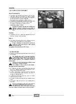
7.8.5 CONTROL COMPONENTES
BARRA PORTARUEDA
X
Controle que la superficie de deslizamiento no esté ra-
yada o tenga hendiduras.
Si las rayas son superficiales, es posible eliminarlas
utilizando papel de lija mojado (de grano 1).
Si las rayas son profundas, sustituya la barra.
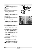
X
Utilice un comparador para controlar que la eventual
curvatura de la barra sea inferior al valor límite.
Si superase el nivel límite, sustituya la barra.
Límite de curvatura: 0,2 mm
NUNCA enderece una barra curvada, en cuan-
to la estructura puede debilitarse, volviendo
peligroso el uso de vehículo.
BOTELLA
X
Controle que no esté dañada y/o fisurada; si así fuera,
sustitúyala.
MUELLE
X
Controle la integridad del muelle, verificando la longi-
tud que debe estar dentro del valor límite.
Antes de medir, golpee el muelle algunas ve-
ces contra un plano limpio para hacerlo reve-
nir.
Longitud del muelle libre: 430 ± 4 mm
7.8.6 INSTALACION
X
Controle que la alineación entre la placa superior e in-
ferior sea perfecta.
Durante el montaje, controle que las superfi-
cies de deslizamiento estén en perfectas con-
diciones (no deben tener señales de desgas-
te, rayas, etc.) en caso contrario, sustituya el
componente.
Durante la instalación tenga cuidado con que
no entren cuerpos extraños en el interior.
No utilice otra vez el aceite descargado ante-
riormente.
Sustituya siempre las juntas.
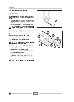
X
+
La botella tiene que introducirse en la placa supe-
rior, hasta que el margen superior quede alineado con
el borde superior de la placa misma.
X
+
Tras la instalación, introduzca por el agujero supe-
rior 430 cm
!
de aceite (barra derecha y barra izquier-
da), véase 1.7 (TABLA DE LOS LUBRICANTES).
X
+
Controle el nivel del aceite, véase 7.8.1 (CONTROL
NIVEL ACEITE).
X
+
Lleve la barra a su extensión máxima.
X
+
Vuelva a colocar el tapón superior (1) con la corres-
pondiente junta tórica.
Una vez concluido el montaje, accione el fre-
no delantero y empuje varias veces sobre la
horquilla.
El funcionamiento tiene que ser suave y progresivo
y, no deben quedar restos de aceite sobre las barras.
7.8.5 CHECKING THE COMPONENTS
WHEEL-HOLDER TUBE
X
Check the sliding surface and make sure that neither
lines, not scratches are present.
Slight lines may be eliminated by means of wet sand-
paper (grain 1).
If the lines are deep, change the fork tube.
X
Using a comparator, make sure that the curving of the
fork tube. if any, is within the limit value.
If it exceeds the limit value, change the fork tube.
Curving limit: 0.2 mm.
NEVER straighten a curved fork tube, since its
structure would be weakened, thus making
the use of the vehicle quite dangerous.
SLIDER
X
Make sure that there are neither damages, nor cracks.
Otherwise, change it.
SPRING
X
Check the soundness of the spring, making sure that
its length is within the limit value.
Before taking the measurement, strike the
spring several times on a hard clean surface,
in order to make it recover its original shape.
Length of the free spring: 430 ± 4 mm
7.8.6 REASSEMBLY
X
Align the upper and lower plate perfectly.
Upon reassembly, pay the greatest attention
and make sure that the sliding surfaces are
in perfect conditions (there must be no signs
of wear, lines, etc.); otherwise, change the compo-
nent.
Avoid any accidental introduction of foreign
matters.
Do not reuse the oil that was drained previ-
ously.
Always change the gaskets.
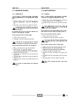
X
+
The slider must be inserted in the upper plate until its
upper edge is aligned with the upper edge of the plate
itself.
X
+
After reassembly, pour 430 cm 3 of oil (right and left
tube) through the upper hole, see 1.7 (LUBRICANT
CHART).
X
+
Check the oil level, see 7.8.1 (CHECKING THE OIL
LEVEL)
X
+
Extend the wheel-holder tube as much as possible.
X
+
Put back the upper plug (1) and the relevant O-ring.
After reassembly, pull the front brake lever
and push the fork down repeatedly.
The operation must be gentle and progressive
and no traces of oil should remain on the fork tubes.
Содержание Pegaso 650
Страница 1: ......
Страница 3: ...0 4 NOTE NOTES ANMERKUNGEN ...
Страница 4: ...1 1 1 2 3 4 5 6 7 8 INFORMAZIONI GENERALI INFORMACIONES GENERALES GENERAL INFORMATION ...
Страница 42: ......
Страница 69: ...3 1 1 2 3 4 5 6 7 8 MOTORE MOTOR ENGINE ...
Страница 90: ...3 22 MOTORE NOTE NOTAS NOTES ...
Страница 91: ...4 1 1 2 3 4 5 SISTEMA DI ALIMENTAZIONE SISTEMA DE ALIMENTACIÓN FUEL SYSTEM ...
Страница 116: ...4 26 SISTEMA DI ALIMENTAZIONE NOTE NOTAS NOTES ...
Страница 117: ...5 1 1 2 3 4 5 6 7 8 IMPIANTO DI RAFFREDDAMENTO SISTEMA DE REFRIGERACIÓN COOLING SYSTEM ...
Страница 130: ...5 14 IMPIANTO DI RAFFREDDAMENTO SISTEMA DE REFRIGERACIÓN COOLING SYSTEM NOTE NOTAS NOTES ...
Страница 131: ...6 1 6 1 2 3 4 5 6 7 8 IMPIANTO ELETTRICO INSTALACIÓN ELÉCTRICA ELECTRICAL SYSTEM ...
Страница 176: ...IMPIANTO ELETTRICO INSTALACIÓN ELÉCTRICA ELECTRICAL SYSTEM 6 46 NOTE NOTAS NOTES ...
Страница 177: ...7 1 1 2 3 4 5 6 7 8 CICLISTICA PARTE CICLO CHASSIS PARTS ...
Страница 226: ... 67 3 57 2 66 6 3 576 7 50 5827 3267 5 25 58 75 6 5 5 5 ...
Страница 242: ... 67 3 57 2 66 6 3 576 7 66 5 12 17 5 25 5 12 17 52 5217 5 ...
Страница 246: ... 67 3 57 2 66 6 3 576 7 70 5 12 3267 5 25 5 12 75 6 52 5 5 5 ...
Страница 272: ... 67 3 57 2 66 6 3 576 7 96 NOTE NOTAS NOTES ...
Страница 273: ...8 1 1 2 3 4 5 6 7 8 INFORMAZIONI PER LE RIPARAZIONI INFORMACIONES PARA LAS REPARACIONES REPAIRS ...
Страница 301: ...INFORMAZIONI PER LE RIPARAZIONI INFORMACIONES PARA LAS REPARACIONES REPAIRS 8 29 E F E F G H G H ...
Страница 302: ...INFORMAZIONI PER LE RIPARAZIONI INFORMACIONES PARA LAS REPARACIONES REPAIRS 8 30 I L I M L N M N ...
Страница 303: ...INFORMAZIONI PER LE RIPARAZIONI INFORMACIONES PARA LAS REPARACIONES REPAIRS 8 31 O P Q P O R Q R ...
Страница 310: ...INFORMAZIONI PER LE RIPARAZIONI INFORMACIONES PARA LAS REPARACIONES REPAIRS 8 38 NOTE NOTAS NOTES ...
Страница 311: ...INFORMAZIONI PER LE RIPARAZIONI INFORMACIONES PARA LAS REPARACIONES REPAIRS 8 39 ...


