5
- 13
SISTEMA DE REFRIGERACIÓN
COOLING SYSTEM
5.5 DESMONTAJE TERMISTOR LIQUIDO
REFRIGERANTE
Lea con cuidado 1.2.5 (LÍQUIDO REFRIGERANTE) y
1.4 (PRECAUCIONES E INFORMACIONES GENERA-
LES).
◆
Coloque el vehículo sobre el caballete.
Deje enfriar el motor hasta que el mismo al-
cance la temperatura ambiente.
◆
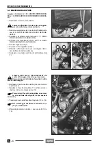
Quite el elemento de protección (1) y desconecte el
terminal eléctrico (2).
◆
Desenrosque y quite el termistor (3).
No quite el tapón del radiador y/o el tapón del
depósito de expansión, de hacerlo el líquido
refrigerante comenzará a salir.
Coloque LOCTITE
®
574 sobre la rosca del ter-
mistor (3) durante la instalación.
Par de apriete termistor (3): 30 Nm (3 kgm).
5.6 DESMONTAJE DEPOSITO DE EXPANSION
Lea con cuidado 1.2.5 (LÍQUIDO REFRIGERANTE) y
1.4 (PRECAUCIONES E INFORMACIONES GENERA-
LES).
◆
Coloque el vehículo sobre el caballete.
Deje enfriar el motor hasta que el mismo al-
cance la temperatura ambiente.
◆
Saque el protector de cárter, véase 7.1.9 (DESMON-
TAJE PROTECTOR DE CARTER).
◆
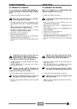
Extraiga el tubo de purga (4) del empalme.
◆
Destornille y quite el tornillo de fijación (5) y guarde la
tuerca.
◆
Destornille y quite el tornillo de fijación (6) y guarde la
arandela.
Hay que realizar bastante rápidamente la ope-
ración descrita a continuación para evitar la
salida, incluso mínima, del líquido del depósito de
expansión (7).
◆
Extraiga el tubo (8) y, a la vez, tape con un dedo el
agujero sobre el depósito de expansión (7).
El líquido refrigerante es nocivo.
Coloque el depósito de expansión (7) en un
lugar seguro.
MANTENGASE LEJOS DEL ALCANCE DE LOS NI-
ÑOS.
◆
Saque el depósito de expansión (7) conservándolo en
posición derecha y guarde el soporte delantero protec-
tor de cárter.
5.7 VALVULA TERMOSTATICA
Consulte el MANUAL DE TALLER DEL MOTOR, N˚ 933
(D-UK) / N˚ 934 (I-E-F).
5.8 BOMBA DE REFRIGERACION
Consulte el MANUAL DE TALLER DEL MOTOR, N˚ 933
(D-UK) / N˚ 934 (I-E-F).
a
c
c
a
c
a
5.5 REMOVING
THE COOLANT THERMISTOR
Read 1.2.5 (COOLANT) and 1.4 (PRECAUTIONS AND
GENERAL INFORMATION) carefully.
◆
Position the vehicle on the stand.
Let the engine cool down until it reaches room
temperature.
◆
Withdraw the protection element (1) and disconnect
the electric terminal (2).
◆
Unscrew and remove the thermistor (3).
Do not remove the radiator cap and/or the ex-
pansion tank cap, otherwise the coolant will
overflow.
Upon reassembly, apply LOCTITE
®
574 on the
thread of the thermistor (3).
Thermistor (3) driving torque: 30 Nm (3kgm).
5.6 REMOVING THE EXPANSION TANK
Read 1.2.5 (COOLANT) and 1.4 (PRECAUTIONS AND
GENERAL INFORMATION) carefully.
◆
Position the vehicle on the stand.
Let the engine cool down until it reaches room
temperature.
◆
Remove the oil pan guard, see 7.1.9 (REMOVING
THE OIL PAN GUARD).
◆
Withdraw the breather pipe (4) from the pipe fitting.
◆
Unscrew and remove the fastening screw (5) and take
the brush.
◆
Unscrew and remove the fastening screw (6) and take
the washer.
The following operation must be performed
rather quickly, in order to avoid even the least
overflow of coolant from the expansion tank (7).
◆
Withdraw the pipe (8) and at the same time plug the
hole on the expansion tank (7) with a finger.
The coolant is noxious.
Put the expansion tank (7) in a safe place.
KEEP AWAY FROM CHILDREN.
◆
Remove the expansion tank (7), keeping it right and
take the oil pan guard front support.
5.7 THERMOSTATIC VALVE
See the ENGINE SERVICE MANUAL, n. 933 (D-UK) / n.
934 (I-E-F).
5.8 COOLING PUMP
See the ENGINE SERVICE MANUAL, n. 933 (D-UK) / n.
934 (I-E-F).
a
c
c
a
c
a
Содержание Pegaso 650
Страница 1: ......
Страница 3: ...0 4 NOTE NOTES ANMERKUNGEN ...
Страница 4: ...1 1 1 2 3 4 5 6 7 8 INFORMAZIONI GENERALI INFORMACIONES GENERALES GENERAL INFORMATION ...
Страница 42: ......
Страница 69: ...3 1 1 2 3 4 5 6 7 8 MOTORE MOTOR ENGINE ...
Страница 90: ...3 22 MOTORE NOTE NOTAS NOTES ...
Страница 91: ...4 1 1 2 3 4 5 SISTEMA DI ALIMENTAZIONE SISTEMA DE ALIMENTACIÓN FUEL SYSTEM ...
Страница 116: ...4 26 SISTEMA DI ALIMENTAZIONE NOTE NOTAS NOTES ...
Страница 117: ...5 1 1 2 3 4 5 6 7 8 IMPIANTO DI RAFFREDDAMENTO SISTEMA DE REFRIGERACIÓN COOLING SYSTEM ...
Страница 130: ...5 14 IMPIANTO DI RAFFREDDAMENTO SISTEMA DE REFRIGERACIÓN COOLING SYSTEM NOTE NOTAS NOTES ...
Страница 131: ...6 1 6 1 2 3 4 5 6 7 8 IMPIANTO ELETTRICO INSTALACIÓN ELÉCTRICA ELECTRICAL SYSTEM ...
Страница 176: ...IMPIANTO ELETTRICO INSTALACIÓN ELÉCTRICA ELECTRICAL SYSTEM 6 46 NOTE NOTAS NOTES ...
Страница 177: ...7 1 1 2 3 4 5 6 7 8 CICLISTICA PARTE CICLO CHASSIS PARTS ...
Страница 226: ... 67 3 57 2 66 6 3 576 7 50 5827 3267 5 25 58 75 6 5 5 5 ...
Страница 242: ... 67 3 57 2 66 6 3 576 7 66 5 12 17 5 25 5 12 17 52 5217 5 ...
Страница 246: ... 67 3 57 2 66 6 3 576 7 70 5 12 3267 5 25 5 12 75 6 52 5 5 5 ...
Страница 272: ... 67 3 57 2 66 6 3 576 7 96 NOTE NOTAS NOTES ...
Страница 273: ...8 1 1 2 3 4 5 6 7 8 INFORMAZIONI PER LE RIPARAZIONI INFORMACIONES PARA LAS REPARACIONES REPAIRS ...
Страница 301: ...INFORMAZIONI PER LE RIPARAZIONI INFORMACIONES PARA LAS REPARACIONES REPAIRS 8 29 E F E F G H G H ...
Страница 302: ...INFORMAZIONI PER LE RIPARAZIONI INFORMACIONES PARA LAS REPARACIONES REPAIRS 8 30 I L I M L N M N ...
Страница 303: ...INFORMAZIONI PER LE RIPARAZIONI INFORMACIONES PARA LAS REPARACIONES REPAIRS 8 31 O P Q P O R Q R ...
Страница 310: ...INFORMAZIONI PER LE RIPARAZIONI INFORMACIONES PARA LAS REPARACIONES REPAIRS 8 38 NOTE NOTAS NOTES ...
Страница 311: ...INFORMAZIONI PER LE RIPARAZIONI INFORMACIONES PARA LAS REPARACIONES REPAIRS 8 39 ...


