7
- 41
3$57(&,&/2
&+$66,63$576
X
Extraiga el basculante junto con la rueda, grupo sus-
pensión y grupo freno , véase 7.9.1 (DESMONTAJE).
X
Desmonte el pedal freno trasero, véase 7.1.24 (DES-
MONTAJE RODILLOS Y PATIN CADENA).
X
Quite el soporte salpicadero, véase 7.1.19 (DESMON-
TAJE SOPORTE SALPICADERO).
X
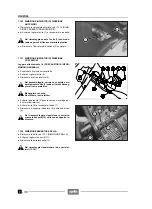
Suspenda el bastidor como indicado en la figura y en-
ganche las cintas a un aparejo de sujeción.
Las cintas y el aparejo de sujeción tienen que
ser adecuados para sostener en toda seguri-
dad el bastidor junto con el tren delantero.
X
Levante el bastidor junto con el avantrén (rueda +
guarda manillar con mandos) lo suficiente
para tener un espacio de unos 250 mm entre la rueda
y el suelo.
X
Extraiga el tren delantero (13) junto con el manguito de
dirección (14), véase 7.7 (DIRECCION).
X
+
Destornille y quite el tornillo (15) y guarde las dos
arandelas.
Par de apriete tornillo (15): 50 Nm (5 kgm)
X
+
Destornille y quite el tornillo (16) y guarde la arande-
la.
Par de apriete tornillo (16): 50 Nm (5 kgm)
X
Quite el soporte superior amortiguador (17).
X
+
Destornille y quite el tornillo (18).
Par de apriete tornillo (18): 80 Nm (kgm)
X
Guarde el estribo piloto y el soporte biela doble (19)
junto con el eventual caballete central
-
.
X
Destornille y quite el tapón del aceite (20) y guarde la
junta tórica (21).
X
Destornille y quite el filtro aceite (22) y guarde la junta
(23).
Par de apriete filtro aceite (22): 35 Nm (3,5 kgm)
X
Destornille y quite el tapón de escape aceite (24) y
guarde la arandela estanca (25).
Par de apriete tapón de escape aceite:
27 Nm (2,7 kgm)
X
Destornille y quite el tornillo (26) y guarde el tampón
(27).
X
Afloje y quite la tuerca, extraiga el tornillo y guarde la
arandela y las dos placas de sujeción motor (28).
Par de apriete tornillo/tuerca de sujeción placas
motor (28): 25 Nm (2,5 kgm).
Al final del reensamblaje del bastidor siga ejecutando es-
tas operaciones:
X
Controle y, eventualmente, ajuste el juego de los coji-
netes de dirección, véase 2.24.1 (CONTROL JUEGO
COJINETES) y 2.24.2 (AJUSTE JUEGO COJINE-
TES).
X
Controle y, eventualmente, ajuste el basculante, véa-
se 2.26 (HORQUILLA TRASERA) y 2.26.1 (AJUSTE
BASCULANTE).
X
Controle la correcta colocación y la sujeción de los tu-
bos y de los cables.
X
Controle la correcta colocación del pedal freno trasero,
véase2.20 (AJUSTE DEL PEDAL DEL FRENO TRA-
SERO).
X
Remove the rear fork complete with wheel, suspension
unit and brake unit, see 7.9.1 (REMOVAL).
X
Remove the rear brake pedal, see 7.1.24 (REMOVING
THE CHAIN ROLLERS AND THE CHAIN SHOE).
X
Remove the dashboard support, see 7.1.19 (REMOV-
ING THE DASHBOARD SUPPORT).
X
Sling the engine as indicated in the figure and hook the
bands to a hoist for support.
The bands and the hoist must be suitable for
bearing the weight of the frame, complete with
forecarriage in total safety.
X
Lift the frame, complete with forecarriage (wheel +
mu fork + handlebars with controls) as much
as necessary to have a distance of about 250 mm be-
tween the wheel and the ground.
X
Withdraw the whole forecarriage (13) from the steering
tube (14), see 7.7 (STEERING).
X
+
Unscrew and remove the screw (15) and take the
two washers.
Screw (15) driving torque: 50 Nm (5 kgm).
X
+
Unscrew and remove the screw (16) and take the
washer.
Screw (16) driving torque: 50 Nm (5 kgm).
X
Remove the shock absorber upper support (17).
X
+
Unscrew and remove the screw (18).
Screw (18) driving torque: 80 Nm (8 kgm).
X
Take the rider’s footboard and the double connecting
rod support (19) complete with the centre stand
-
, if
this is provided.
X
Unscrew and remove the oil plug (20) and take the O-
ring (21).
X
Unscrew and remove the oil filter (22) and take the
gasket (23).
Oil filter (22) driving torque: 35 Nm (3.5 kgm).
X
Unscrew and remove the oil drain plug (24) and take
the sealing washer (25).
Oil drain plug (24) driving torque: 27 Nm (2.7 kgm).
X
Unscrew and remove the screw (26) and take the buff-
er (27).
X
Loosen and remove the nut, withdraw the screw and
take the washer and the two engine support plates
(28).
Driving torque of the engine support plate (28) fas-
tening screw/nut: 25 Nm (2.5 kgm).
Once the frame has been completely reinstalled, proceed
to the following operations:
X
Check and if necessary adjust the steering bearing
slacks, see 2.24.1 (CHECKING THE BEARING
SLACKS) and 2.24.2 (ADJUSTING THE BEARING
SLACKS).
X
Check and if necessary adjust the rear fork, see 2.26
(REAR FORK) and 2.26.1 (ADJUSTING THE REAR
FORK).
X
Make sure that pipes and cables are correctly posi-
tioned and fastened.
X
Make sure that the rear brake pedal is positioned cor-
rectly, see 2.20 (REAR BRAKE PEDAL ADJUST-
MENT).
Содержание Pegaso 650
Страница 1: ......
Страница 3: ...0 4 NOTE NOTES ANMERKUNGEN ...
Страница 4: ...1 1 1 2 3 4 5 6 7 8 INFORMAZIONI GENERALI INFORMACIONES GENERALES GENERAL INFORMATION ...
Страница 42: ......
Страница 69: ...3 1 1 2 3 4 5 6 7 8 MOTORE MOTOR ENGINE ...
Страница 90: ...3 22 MOTORE NOTE NOTAS NOTES ...
Страница 91: ...4 1 1 2 3 4 5 SISTEMA DI ALIMENTAZIONE SISTEMA DE ALIMENTACIÓN FUEL SYSTEM ...
Страница 116: ...4 26 SISTEMA DI ALIMENTAZIONE NOTE NOTAS NOTES ...
Страница 117: ...5 1 1 2 3 4 5 6 7 8 IMPIANTO DI RAFFREDDAMENTO SISTEMA DE REFRIGERACIÓN COOLING SYSTEM ...
Страница 130: ...5 14 IMPIANTO DI RAFFREDDAMENTO SISTEMA DE REFRIGERACIÓN COOLING SYSTEM NOTE NOTAS NOTES ...
Страница 131: ...6 1 6 1 2 3 4 5 6 7 8 IMPIANTO ELETTRICO INSTALACIÓN ELÉCTRICA ELECTRICAL SYSTEM ...
Страница 176: ...IMPIANTO ELETTRICO INSTALACIÓN ELÉCTRICA ELECTRICAL SYSTEM 6 46 NOTE NOTAS NOTES ...
Страница 177: ...7 1 1 2 3 4 5 6 7 8 CICLISTICA PARTE CICLO CHASSIS PARTS ...
Страница 226: ... 67 3 57 2 66 6 3 576 7 50 5827 3267 5 25 58 75 6 5 5 5 ...
Страница 242: ... 67 3 57 2 66 6 3 576 7 66 5 12 17 5 25 5 12 17 52 5217 5 ...
Страница 246: ... 67 3 57 2 66 6 3 576 7 70 5 12 3267 5 25 5 12 75 6 52 5 5 5 ...
Страница 272: ... 67 3 57 2 66 6 3 576 7 96 NOTE NOTAS NOTES ...
Страница 273: ...8 1 1 2 3 4 5 6 7 8 INFORMAZIONI PER LE RIPARAZIONI INFORMACIONES PARA LAS REPARACIONES REPAIRS ...
Страница 301: ...INFORMAZIONI PER LE RIPARAZIONI INFORMACIONES PARA LAS REPARACIONES REPAIRS 8 29 E F E F G H G H ...
Страница 302: ...INFORMAZIONI PER LE RIPARAZIONI INFORMACIONES PARA LAS REPARACIONES REPAIRS 8 30 I L I M L N M N ...
Страница 303: ...INFORMAZIONI PER LE RIPARAZIONI INFORMACIONES PARA LAS REPARACIONES REPAIRS 8 31 O P Q P O R Q R ...
Страница 310: ...INFORMAZIONI PER LE RIPARAZIONI INFORMACIONES PARA LAS REPARACIONES REPAIRS 8 38 NOTE NOTAS NOTES ...
Страница 311: ...INFORMAZIONI PER LE RIPARAZIONI INFORMACIONES PARA LAS REPARACIONES REPAIRS 8 39 ...

