hypercharger - Operation Instructions and Installation Guide
Version 1-1C
Content
All rights reserved. The reproduction of this document, also partially, is allowed only with authorization by alpitronic s.r.l.
List of figures
Figure 1: Example of Nameplate for hypercharger ............................................................. 4
Figure 2: Vertical and horizontal transport with pallet truck or forklift .................................. 6
Figure 3: Crane eyelets on top of the packaging ................................................................ 6
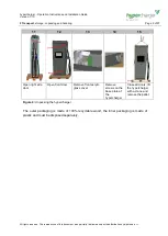
Figure 4: Unpacking the hypercharger ............................................................................... 9
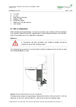
Figure 5: Elements of the charging station ........................................................................10
Figure 6: Recommended distances for site configuration ..................................................11
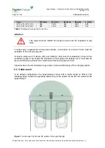
Figure 7: Cable reach for the two DC outlets of the hypercharger .....................................12
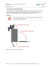
Figure 8: Order for opening the hypercharger ...................................................................13
Figure 9: Internal view hypercharger HYC_075 and HYC_150 (left, front and right) ..........14
Figure 10: DC output switchgear of the HYC_075 and the HYC_150 ................................16
Figure 11: AC input switchgear of the HYC_075 and the HYC_150 ..................................17
Figure 12: Internal view hypercharger HYC_225 and HYC_300 (left, front and right) ........18
Figure 13: DC output switchgear of the HYC_225 and the HYC_300 (bottom view) .........19
Figure 14: DC output switchgear of the HYC_225 and the HYC_300 (top view) ...............20
Figure 15: AC input switchgear of the HYC_225 and the HYC_300 ..................................21
Figure 16: hypercharger configurations and options .........................................................22
Figure 17: DC output power of the 75kW hypercharger ....................................................23
Figure 18: DC output power of the 150kW hypercharger, whole DC-power on one outlet .23
Figure 19: DC output power of the 225kW hypercharger ..................................................24
Figure 20: DC output power of the 300kW hypercharger, whole DC-power on one outlet .25
Figure 21: Naming of relevant components for the mechanical installation of the
hypercharger ....................................................................................................................26
Figure 22: Distances between base plate and outer dimensions of charging station on the
concrete foundation (HYC_075, HYC_150) (front/top view) ..............................................27
Figure 23: Distances between base plate and outer dimensions of charging station on the
concrete foundation (HYC_225, HYC_300) (front/top view) ..............................................28
Figure 24: hypercharger-base for the HYC_075 and HYC_150 (front/top view left) ..........29
Figure 25: hypercharger-base for the HYC_225 and HYC_300 (front/top view left) ..........29
Figure 26: hypercharger schematic for the HYC_075 and the HYC_150...........................31
Figure 27: hypercharger schematic for the HYC_225 and the HYC_300...........................32
Figure 28: Cable inlet and connection lengths for HYC_075 to HYC_300 .........................33
Figure 29: Connecting of the input Busbars (HYC_075/150 left, HYC_225/300 right) .......34
Figure 30: Credentials form shown at first connection with web interface..........................36
Figure 31: Home screen of web interface ..........................................................................37
Figure 32: Example of SIM Signal webpage .....................................................................39
Figure 33: Example of Process View webpage .................................................................40
Figure 34: Example of Stop Button webpage ....................................................................41
Figure 35: Example of BOOT Configuration webpage .......................................................42
Figure 36: Example of OCPP Configuration webpage.......................................................43
Figure 37: Example of GUI Configuration webpage ..........................................................44
Figure 38: Example of Ethernet Configuration webpage ...................................................45
Figure 39: Example of SIM Configuration webpage ..........................................................46
Figure 40: Example of the Password Configuration webpage ...........................................46
Figure 41: Replacing a Power-Stack .................................................................................49
Figure 42: Cooling unit for cooled charging cable (option) ................................................50


