hypercharger - Operation Instructions and Installation Guide
Version 1-1C
3
Product
description
Page 11 of 57
All rights reserved. The reproduction of this document, also partially, is allowed only with authorization by alpitronic s.r.l.
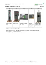
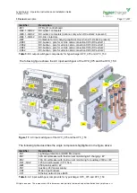
D
air outlet
E
air inlet
F
Stop button (optional)
G
Display / HMI
H
RFID card reader
I
GSM / LTE / WLAN antenna
J
door handle
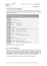
3.2. Site Configuration
When installing the hypercharger, it must be ensured to give certain a minimum distance
from possible objects around the hypercharger, to allow adequate airflow, and secondly,
space for possible service or maintenance operations.
Attention
A mechanical ramming protection with sufficient stability should be
provided to protect the charging station.
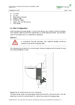
The following figure shows the recommended minimum distances which should be kept
free during installation on site:
Figure 6:
Recommended distances for site configuration
The figure above shows the hypercharger housing for the HYC_075 and the HYC_150, the
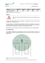
distances for the HYC_225 and the HYC_300 can be found in the following table.


