


hypercharger - Operation Instructions and Installation Guide
Version 1-1C
Page 34 of 57
5
Electrical
installation
All rights reserved. The reproduction of this document, also partially, is allowed only with authorization by alpitronic s.r.l.
5.4. Grid Connection
The hypercharger charging stations can be used in supply networks of the type TT and
TN-S.
Attention
The necessary protective measures against electric shock and other
country-specific requirements must be taken into account.
Depending on the configuration of the hypercharger and the EMC
measures, the protective conductor current can cause protective
conductor currents up to 1A. Please take this into account when
designing the protective earthing and protective measures.
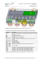
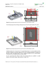
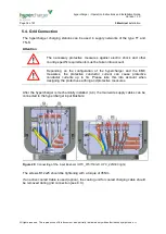
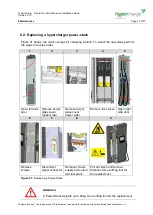
After the hypercharger is mechanically installed (4.4), the main-side supply cables can be
connected to the hypercharger input Busbars:
Figure 29:
Connecting of the input Busbars (HYC_075/150 left, HYC_225/300 right)
The screws M12x25 should be tightening with a torque of 35Nm.
If an active cooled Cable is used (option), the cooling unit for cooled charging cable should
be removed during grid connection (see 8.3.).


