


hypercharger - Operation Instructions and Installation Guide
Version 1-1C
Page 20 of 57
3
Product
description
All rights reserved. The reproduction of this document, also partially, is allowed only with authorization by alpitronic s.r.l.
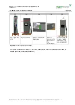
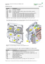
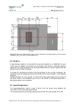
Figure 14:
DC output switchgear of the HYC_225 and the HYC_300 (top view)
The following table describes the single components highlighted in the table above:
Identifier
Description
-BC1
DC fault current monitoring for AC charging (optional, only when AC-socket is
present)
-BE1
DC-meter for DC-outlet 1
-BE2
DC-meter for DC-outlet 2 (optional)
-BE3
AC meter
-BX1.1, -BX2.1
DC-outlet 1 isolation monitoring device
-BX2.2, -BX1.2
DC-outlet 1 isolation monitoring device (optional, only when DC-outlet 2 is
present)
-FC1.1, FC1.2
DC-outlet 1 fuses
-FC2.1, FC2.2
DC-outlet 2 fuses
-KF3
CTRL_IO control board
-QB2.1, -QB2.2
DC-outlet 1 contactors
-QB3.1, -QB3.2
DC-outlet 2 contactors (optional, only when DC-outlet 2 is present)
-QB4.1, -QB4.2
-QB5.1, -QB5.2
-QB6.1, -QB5.2
DC-link contactors
-QB7
Contactors for AC charging (optional, only when AC-socket is present)
-XD3.1
DC- pole for vehicle cable connection XD5 (DC-outlet 1)
-XD3.2
DC-busbar
– pole for vehicle cable connection XD5 (DC-outlet 1)
-XD4.1
DC- pole for vehicle cable connection XD6 (DC-outlet 2)
-XD4.2
DC-busbar
– pole for vehicle cable connection XD6 (DC-outlet 2)
Table 8:
DC output switchgear components for hypercharger HYC_225 and HYC_300


