


hypercharger - Operation Instructions and Installation Guide
Version 1-1C
Page 14 of 57
3
Product
description
All rights reserved. The reproduction of this document, also partially, is allowed only with authorization by alpitronic s.r.l.
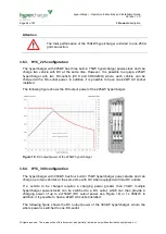
3.5. Internal view
3.5.1.
HYC_075 and HYC_150 internal view
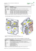
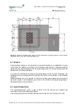
The following figure shows the hypercharger
’s internal view for the HYC_075 and the
HYC_150 configurations.
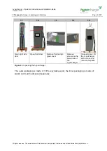
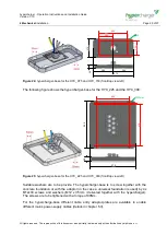
Figure 9:
Internal view hypercharger HYC_075 and HYC_150 (left, front and right)
The following table describes the single components highlighted in the figures above:
Identifier
Description
-BC1
DC fault current monitoring for AC charging (optional, only when AC-socket is
present)
-BE3
AC meter
-BX1.1, -BX2.1
DC-outlet 1 isolation monitoring device
-BX2.2, -BX1.2
DC-outlet 1 isolation monitoring device (optional, only when DC-outlet 2 is
present)
-EP1
Cooling unit for cooled charging cable (optional, only with cooled charging
cable)
-FB1
32A circuit breaker with fault current monitoring AC charging / 4P
-FB2
16A circuit breaker for auxiliary 230Vac / 4P
-KF1, -KF2
CTRL_COM_HD control board, CTRL_COM Display


