


hypercharger - Operation Instructions and Installation Guide
Version 1-1C
4
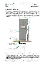
Mechanical
installation
Page 27 of 57
All rights reserved. The reproduction of this document, also partially, is allowed only with authorization by alpitronic s.r.l.
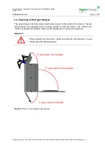
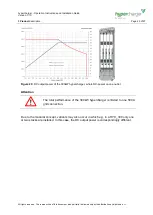
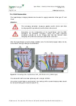
Attention
Before installation, compliance with all legal requirements for the
installation site (for example, stability against tipping, impact protection,
effects of frost, etc.) must be checked.
Each outlet or each vehicle clutch must be arranged in consideration of
the ergonomics and mechanical impact protection, as close as possible
to the car park to be supplied.
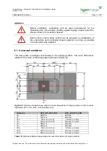
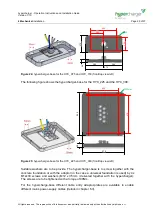
4.1. Concrete foundation
The base plate is arranged eccentrically to the charging station. The outer dimensions
related to the center of the base plate are shown in Figure 22.
Figure 22:
Distances between base plate and outer dimensions of charging station on the concrete
foundation (HYC_075, HYC_150) (front/top view)
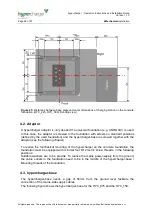
Distance
HYC_075, HYC_150
HYC_225, HYC_300
D
C
420 mm
420 mm
D
I
100 mm
235 mm
D
IB
36 mm (
±
3 mm)
36 mm (
±
3 mm)
D
O
210 mm (
±
3 mm)
366 mm (
±
3 mm)
W
C
300 mm
300 mm
W
I
200 mm
200 mm
W
IB
86 mm (
±
3 mm)
86 mm (
±
3 mm)
W
OL
357 mm (
±
3 mm)
357 mm (
±
3 mm)
W
OR
519 mm (
±
3 mm)
516 mm (
±
3 mm)
Table 10:
Distances between base plate and outer dimensions of charging station


