


hypercharger - Operation Instructions and Installation Guide
Version 1-1C
5
Electrical
installation
Page 33 of 57
All rights reserved. The reproduction of this document, also partially, is allowed only with authorization by alpitronic s.r.l.
5.3. Preparation mains power-supply cables
After the hypercharger-base (see chapter 4.3) is mounted, the mains-side cables should
be conducted through foundation and hypercharger-base. Then the mains-side cables
should be fixed by tightening the cable gland.
For the hypercharge-base different cable entry adaptor-plates are available to enable
different mains power-supply cable types:
Single supply cable
Multiple supply cable
HYC_075 / HYC_150
1 x M65 Hole for 3 different cable
glands with a clamping range of:
27-39mm
34-45mm
44-55mm
1 x M20 Hole for a cable gland
with a clamping range of:
7-13mm
5 x M40 Hole for cable glands
with a clamping range of:
19-28mm
1 x M20 Hole for cable glands
with a clamping range of:
7-13mm
HYC_225 / HYC_300
2 x M65 Hole for 3 different cable
glands with a clamping range of:
27-39mm
34-45mm
44-55mm
1 x M20 Hole for a cable gland
with a clamping range of:
7-13mm
8 x M40 Hole for cable glands
with a clamping range of:
19-28mm
1 x M20 Hole for cable glands
with a clamping range of:
7-13mm
Table 11:
Available cable entry adaptor plates for hypercharger-base (
not available yet
)
The necessary cable entry adaptor plate depends on the used mains power-supply cable
and should be defined during the ordering of the hypercharger.
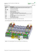
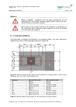
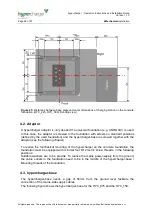
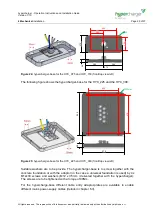
Afterwards the M12 cable lugs can be mounted on the positions defined in Figure 28.
Figure 28:
Cable inlet and connection lengths for HYC_075 to HYC_300


