


hypercharger - Operation Instructions and Installation Guide
Version 1-1C
Page 32 of 57
5
Electrical
installation
All rights reserved. The reproduction of this document, also partially, is allowed only with authorization by alpitronic s.r.l.
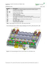
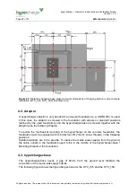
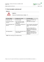
5.2. hypercharger schematic for the HYC_225 and the HYC_300
The following figure shows the schematic of the hypercharger for the HYC_225 and the
HYC_300:
DC-output
switchgear
AC input
switchgear
400V ~
24V
DC
CTRL_COM
Display
STACK
(AC/DC)
(HYC_300
only)
4
lightning
protection
main
switch
3
CCS or
CHADEMO
CCS or
CHADEMO
AC-CCS
2
STACK
(AC/DC)
-FC2
2
2
2
4
STACK
(AC/DC)
STACK
(AC/DC)
2
2
GRID
-KF1
-TB1
-QB1
125A
10kA
3
125A
10kA
3
125A
10kA
3
125A
10kA
3
-QA4
-QA3
-QA2
-QA1
-FB1
-FB2
30mA/16A
10kA
4
30mA/32A
10kA
4
-FA1
-TB5
-TB4
-TB3
-TB2
-QB3
-QB2
-QB6
-QB5
-QB4
-QB7
-BX2
-BX1
<R
<R
-FC1
-XD1
3+N+PE
-XD2
-XD4
-XD3
-KF3
2
2
-BE3
Wh
-BE2
Wh
I/U
-BE1
Wh
I/U
-TF1
CTRL_COM
HD
-KF2
STOP
Door contact
-XF1
Ethernet
(RJ45)
-SF2 -SF3
-SF1
Power socket
230Vac
4
-XD5
-XD6
-XD7
HYC
-BC1
D
I<6mA
CTRL_IO
AC-Charging
(optional)
(option)
(option)
-EP1
(option)
Cooling unit
M
M
Figure 27:
hypercharger schematic for the HYC_225 and the HYC_300


