


BREAKER ME10
TRIP UNIT
OPER
A
TION
2
.2
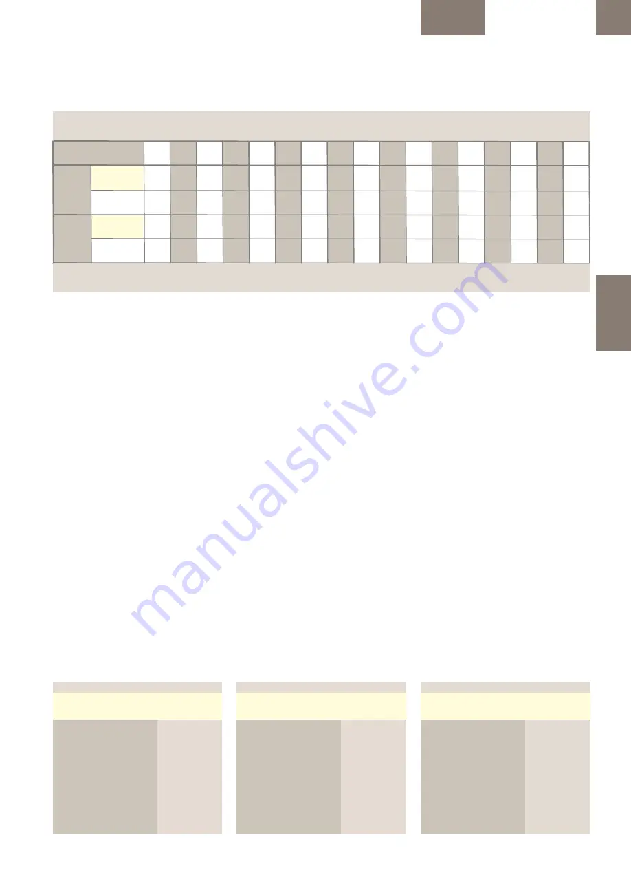
Tabella 2.6: Dispositivi HSIOC
| Valori impostati (rms)
Dispositivi HSIOC
installati sugli
interruttori:
Taglia T:
AT04R ... AT16R
43.000A
AT04K ... AT16K
51.500A
Taglia 1
AG04 S ... AG20S
50.000 A
AG04N ... AG20N
65.000 A
Taglia 2
AG25N ... AG40N
65.000 A
AG04E ... AG20E
85.000 A
AG25H ... AG40H
85.000 A
AG25M ... AG40M
85.000 A
Taglia 3
AG32G ... AG40G
100.000 A
AG40M ... AG64M
100.000 A
AG40L ... AG64L
100.000 A
2-13
2.2.3.1.1 Regolazione lungo riardo
(Sulla protezione da sovraccarico) tr
I Relè di Protezione ME10 offrono 22 curve di
lungo ritardo che hanno un profilo simile a
quello dell'elemento termico di un interruttore
magnetotermico.
I Relè di Protezione ME10 GT-H offrono quattro
tipi di banda alternativi:
1) 22 bande di ritardo che offrono una forma
simile a quella di fusibili standard.
2) 13 bande inverse standard secondo IEC 255.
3) 13 bande inverse superiori secondo IEC 255.
4) 13 bande inverse estreme secondo IEC 255.
I minimi e massimi tempi di ritardo e la loro
classificazione IEC 947 sono indicati in tabella
2.3.
Tutti i tipi di banda sono sono rappresentati in
tempo/corrente nei diagrammi nel capitolo 2.5
di questo manuale.
2.2.3.2 Intervento a corto ritardo
(Protezione da corto circuito ritardata) SD
La seconda schermata in modalità di CONFIG è
sempre l'impostazione dell'intervento a corto
ritardo, installata in tutti i tipi di Relè di
Protezione, La funzione intervento a corto
ritardo stabilisce la corrente alla quale si attiva
l'intervento temporizzato a corto ritardo (Isd) e
viene regolata in funzione delle impostazioni
dell'intervento a lungo ritardo Ir. Le scelte di
impostazione dell'intervento vanno da 1,5 a 12,0
(1) volte l'impostazione del lungo ritardo, x Ir, a
passi di 0,5 x Ir. Consultare la tabella 2.5.
La banda di tolleranza del valore di intervento
SD (Isd) va da -10% a +10% dell'impostazione.
Un ulteriore riduzione della precisione del ± 5% è
ammessa per le forme d'onda con una
significativa distorsione armonica.
Table 2.5 : Short Time tripping times at indicated levels per selected tsd band -I²t OFF. in ms (2)
Tab. 2.5: Kurzzeit-Auslösung...
Tabella 2.5: Tempi di intervento a corto ritardo ai livelli indicati per curva tsd selezionata - I²t OFF. in ms (2)
740
840
940
340
390
540
640
180
210
240
280
800
900
1000
30
40
50
60
110
130
400
450
600
700
240
270
300
340
840
940
12 x
±10%
90
100
110
120
170
190
390
540
640
740
210
240
280
340
900
1000
Non Tripping
Keine Auslösung
Non intervento
30
40
50
60
110
130
180
450
600
700
800
270
300
340
400
Max
1.5 x
±10%
Tripping
Auslösung
Intervento
90
100
110
120
170
190
240
13
14
15
16
9
10
11
12
x Ir
Min
2
3
4
5
6
7
8
(1) On Envelope 3 type limited to 10 x Ir. (2) Timings in Red meet the requirements of the IEC 60479-1 and IEC 60364 standards at a frequency of 50 cycles.
(1) Baugröße 3 limitiert auf 10 x Ir.
(2) Rote Eintragungen stimmen mit den Anforderungen von IEC 60479 mit einer Frequenz von 50 Hz überein.
(1) Sulla Taglia tipo 3 limitato a 10 x Ir.
(2) I tempi in rosso soddisfano i requisiti delle norme IEC 60479-1 e IEC 60364 ad una frequenza di 50 cicli.
Non Tripping
Keine Auslösung
Non intervento
Tripping
Auslösung
Intervento
2.2.3.1.1 Long Time Delay
(On overload Protection) tr
All ME10 trip unit types offer 22 long time delay
bands that have a shape similar to that of the
thermal element of a thermal magnetic circuit
breaker.
The GT-H & HE ME10 Trip Unit models offer four
alternate band types:
1) 22 delay bands offering a shape
similar to that of standard fuses.
2) 13 Standard Inverse bands
in accordance with IEC 255.
3) 13 Very Inverse bands
in accordance with IEC 255.
4) 13 Extremely inverse bands
in accordance with IEC 255.
The minimum and max. delay times and their
IEC 947 classification are indicated in table 2.3.
All band type are are depicted as Time Current
Diagram in chapter 2.5 of this Application
manual.
2.2.3.2 Short Time Pickup
(Delayed Short Circuit Protection) SD
Installed in all Trip Units types the second SETUP
mode display is always the Short Time Pickup set
point. The Short Time Pickup function
establishes the current at which a timed short
time trip is activated (I ) and is adjusted in
sd
function of the Long Time Pickup setting Ir. The
choices of pickup settings are from 1.5 to 12.0 (1)
times the long time setting, x Ir ( Ir) , in steps of
0.5 x Ir (Ir). see table 2.5.
The SD pickup value (I ) tolerance band is -10%
sd
to +10% of the set point. An additional accuracy
degradation of ±5% shall be allowed for
waveforms with significant harmonic distortion.
2.2.3.1.1 Langzeitverzögerung
(für Überlastschutz) tr
Alle ME10 Auslöseeinheiten bieten 22 Langzeit-
Verzögerungsbereiche, die der Verzögerungsart
der thermischen Elemente eines therm.-magn.
Leistungsschalter ähneln.
Die GT-H & HE ME10 Modelle bieten 4
alternative Verzögerungstypen:
1) 22 Verzögerungsbereiche bieten eine ähnliche
Verzögerungsart wie die Standard-Sicherungen.
2) 13 Standard Inverse Bereiche
in Übereinstimmung mit IEC 255.
3) 13 Sehr Inverse Bereiche
in Übereinstimmung mit IEC 255.
4) 13 Extrem inverse Bereiche
in Übereinstimmung mit IEC 255.
Die minimalen und max. Verzögerungszeiten
und ihre IEC 947 Klassifikation ist in Tab. 2.3
aufgezeigt.
Die Bereiche sind dargestellt als Zeit-Strom-
Diagramm im Kapitel 2.5.
2.2.3.2 Kurzzeitverzögerung
(verzögerter Kurzschlussschutz) SD
In allen Arten von Auslöseeinheiten zeigt der
zweite SETUP-Modus immer den
Kurzzeitverzögerungs-Einstellwert. Durch die
Kurzzeitverzögerungs-Funktion wird der Strom
gesetzt, auf dem eine zeitliche Kurzzeit-
Auslösung aktiviert (I ) ist, in Abhängigkeit zur
sd
Langzeitauslösungs-Einstellung Ir. Die Wahl der
Einstellungen liegt zwischen 1,5 und 12,0 (1) mal
der Langzeit-Einstellung, x Ir (Ir), in Schritten von
0,5 x Ir (Ir). siehe Tab. 2.5.
Der SD Einstellwert (I )-Toleranzbereich beträgt -
sd
10% bis +10% des Einstellwertes. Eine
zusätzliche Genauigkeitsabweichung von ± 5%
tritt für Kurvenformen mit erheblicher
harmonischer Verzerrung ein.
Table 2.6: HSIOC devices |
Set values (rms)
Overview of installed
HSIOC devices in
Automatic types:
Envelope T: AT04R ... AT16R
43.000A
AT04K ... AT16K
51.500A
Envelope 1: AG04 S ... AG20S
50.000 A
AG04N ... AG20N
65.000 A
Envelope 2: AG25N ... AG40N
65.000 A
AG04E ... AG20E
85.000 A
AG25H ... AG40H
85.000 A
AG25M ... AG40M
85.000 A
Envelope 3: AG32G ... AG40G
100.000 A
AG40M ... AG64M
100.000 A
AG40L ... AG64L
100.000 A
Tab. 2.6: HSIOC Schutz |
Werte (rms)
Übersicht über
HSIOC Geräte in
Automatik Typen:
Baugröße T: AT04R ... AT16R
43.000A
AT04K ... AT16K
51.500A
Baugröße 1: AG04 S ... AG20S
50.000 A
AG04N ... AG20N
65.000 A
Baugröße 2: AG25N ... AG40N
65.000 A
AG04E ... AG20E
85.000 A
AG25H ... AG40H
85.000 A
AG25M ... AG40M
85.000 A
Baugröße 3: AG32G ... AG40G
100.000 A
AG40M ... AG64M
100.000 A
AG40L ... AG64L
100.000 A


