


MC97F6108A User’s manual
6. Interrupt controller
51
6.4
Interrupt vector table
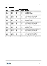
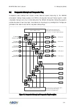
Interrupt controller of MC97F6108A supports 23 interrupt sources as shown in Table 8. When interrupt
is served, long call instruction (LCALL) is executed and program counter jumps to the vector address.
All interrupt requests have their own priority order.
Table 8. Interrupt Vector Address Table
Interrupt source
Symbol
Interrupt
Enable bit
Priority
Mask
Vector
address
Hardware Reset
RESETB
―
0
Non-Maskable
0000H
External Interrupt 0
INT0
IE.0
1
Maskable
0003H
External Interrupt 1
INT1
IE.1
2
Maskable
000BH
External Interrupt 2
INT2
IE.2
3
Maskable
0013H
PCI Interrupt
INT3
IE.3
4
Maskable
001BH
ATP_MIN Interrupt
INT4
IE.4
5
Maskable
0023H
ATP_MAX Interrupt
INT5
IE.5
6
Maskable
002BH
CMP0 Interrupt
INT6
IE1.0
7
Maskable
0033H
CMP1 Interrupt
INT7
IE1.1
8
Maskable
003BH
CMP2 Interrupt
INT8
IE1.2
9
Maskable
0043H
CMP3 Interrupt
INT9
IE1.3
10
Maskable
004BH
CMP4 Interrupt
INT10
IE1.4
11
Maskable
0053H
I2C Interrupt
INT11
IE1.5
12
Maskable
005BH
RXD Interrupt
INT12
IE2.0
13
Maskable
0063H
TXD Interrupt
INT13
IE2.1
14
Maskable
006BH
T0 Interrupt
INT14
IE2.2
15
Maskable
0073H
T1 Interrupt
INT15
IE2.3
16
Maskable
007BH
T2 Interrupt
INT16
IE2.4
17
Maskable
0083H
T3 Interrupt
INT17
IE2.5
18
Maskable
008BH
PPG Interrupt
INT18
IE3.0
19
Maskable
0093H
ADC Interrupt
INT19
IE3.1
20
Maskable
009BH
WDT Interrupt
INT20
IE3.2
21
Maskable
00A3H
BIT Interrupt
INT21
IE3.3
22
Maskable
00ABH
BOD Interrupt
INT22
IE3.4
23
Maskable
00B3H
-
INT23
IE3.5
24
Maskable
00BBH
For maskable interrupt execution, EA bit must set ‘1’ and specific interrupt must
be enabled by writing
‘1’ to associated bit in the IEx. If
an interrupt request is received, the specific interrupt request flag is
set to
‘1’. And it remains ‘1’ until CPU accepts interrupt.
If the interrupt is served, the interrupt request
flag will be cleared automatically.