


MC97F6108A User’s manual
5. I/O ports
41
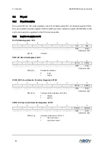
PSR3 (Analog I/O port Selection Register): 2F4BH
7
6
5
4
3
2
1
0
-
-
PSR35
PSR34
PSR33
PSR32
PSR31
-
-
-
R/W
R/W
R/W
R/W
R/W
R/W
Initial value: 00H
PSR35
P2[1] Analog Input selection register
0
P2[1] digital input (default)
1
P2[1] AMP1I input
PSR34
P1[6] Analog Input selection register
0
P1[6] digital input (default)
1
P1[6] CMP0_IN_N input
PSR33
P1[5] Analog Input selection register
0
P1[5] digital input (default)
1
P1[5] CMP0_IN_P input
PSR32
P1[4] Analog Input selection register
0
P1[4] digital input (default)
1
P1[4] CMP2_IN_P input
PSR31
P1[3] Analog Input selection register
0
P1[3] digital input (default)
1
P1[3] CMP1_IN_P input
NOTES:
1.
It is recommended to set this register when using port as Analog input such as
ADC input, Comparator input, or OP-Amp input/output. And do not set this register
when port is used as digital input.
2.
PSR3[0] must be kept '0'.