


MC97F6108A User’s manual
15. USART
149
15.2
Clock generation
Clock generation logic generates a base clock signal for Transmitter and Receiver. USART supports
four modes of clock operation such as Normal Asynchronous mode, Double Speed Asynchronous mode,
Master Synchronous mode, and Slave Synchronous mode.
Clock generation scheme for Master SPI and Slave SPI mode is the same as Master Synchronous and
Slave Synchronous operation mode. UMSELn bit in UCTRL1 register selects between asynchronous
and synchronous operation. Asynchronous Double Speed mode is controlled by the U2X bit in the
UCTRL2 register.
The MASTER bit in UCTRL2 register controls whether the clock source is internal (Master mode, output
port) or external (Slave mode, input port). The XCK pin is only active when the USART operates in
Synchronous or SPI mode.
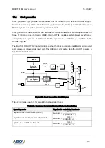
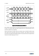
Figure 67. Clock Generation Block Diagram
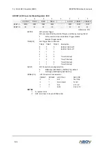
Table 20 contains equations for calculating the baud rate (in bps).
Table 20. Equations for Calculating Baud Rate Register Setting
Operating mode
Equation for calculating baud rate
Asynchronous normal mode (U2X=0)
Baud Rate =
fSCLK
16( 1)
Asynchronous double speed mode (U2X=1)
Baud Rate =
fSCLK
8( 1)
Synchronous or SPI master mode
Baud Rate =
fSCLK
2( 1)
XCK
Prescaling
Up-Counter
UBAUD
/2
/8
Sync Register
/2
SCLK
f
SCLK
(UBAUD+1)
txclk
rxclk
UMSEL0
U2X
MASTER
UCPOL