


MC97F6108A User’s manual
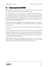
12. Analog comparator and OP-AMP
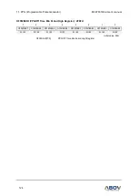
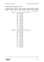
127
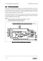
Comparator 3
"+" input is the output of the AMP1
"-" input is internal Vref selected by setting C3NVSL[3:0] register.
Output(CPOUT3) generates interrupt flag(CMP3IF) and comparator flag(C3_FLAG).
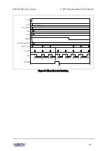
CPOUT3 is connected to the timer 3 event counter source.
CMP3IF is connected to a capture source of the timer 3 and PPG.
C3_FLAG is used to disable PPG output.
Comparator 4
"+" input is external analog port shared with comparator1(CMP1_IN_P).
"-" input is internal Vref selected by setting C4NVSL[2:0] register.
Output(CPOUT4) generates interrupt flag(CMP4IF) and comparator flag(C4_FLAG).
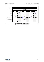
CMP4IF is connected to a capture source of the PPG.
AMP1
"+" input is external analog port AMP1I.
Output is connected to the comparator 3 and AMP2 input.
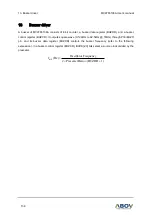
The gain is selected by setting DGCAL1[2:0] register.
AMP2
"+" input is output of AMP1.
Output is connected to AMP2O port and AN5 (ADC channel 5).
The gain is selected by setting DGCAL2[2:0] register.