


16. Inter Integrated Circuit (I2C)
MC97F6108A User’s manual
182
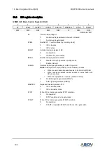
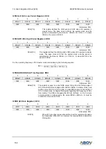
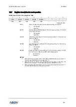
I2CSCLLR (SCL Low Period Register): DCH
7
6
5
4
3
2
1
0
SCLL7
SCLL6
SCLL5
SCLL4
SCLL3
SCLL2
SCLL1
SCLL0
R/W
R/W
R/W
R/W
R/W
R/W
R/W
R/W
Initial value: 3FH
SCLL[7:0]
This register defines the LOW period of SCL when I2C operates in
master mode. The base clock is SCLK, the system clock, and the
period is calculated by the formula : tSCLK× (4 × SCLL + 1) where
tSCLK is the period of SCLK
I2CSCLHR (SCL High Period Register): DDH
7
6
5
4
3
2
1
0
SCLH7
SCLH6
SCLH5
SCLH4
SCLH3
SCLH2
SCLH1
SCLH0
R/W
R/W
R/W
R/W
R/W
R/W
R/W
R/W
Initial value: 3FH
SCLH[7:0]
This register defines the HIGH period of SCL when I2C operates in master
mode. The base clock is SCLK, the system clock, and the period is
calculated by the formula: tSCLK× (4 × SCLH + 3) where tSCLK is the
period of SCLK.
So, the operating frequency of I2C master mode is calculated by the following equation.
fI2C =
1
tSCLK × (4(SCLL + SCLH) + 4)
I2CSDAHR (SDA Hold Time Register): DEH
7
6
5
4
3
2
1
0
SDAH7
SDAH6
SDAH5
SDAH4
SDAH3
SDAH2
SDAH1
SDAH0
R/W
R/W
R/W
R/W
R/W
R/W
R/W
R/W
Initial value: 01H
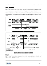
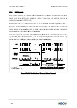
SDAH[7:0]
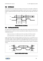
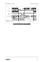
This register is used to control SDA output timing from the falling edge of
SCL. Note that SDA is changed after tSCLK× SDAH. In master mode, load
half the value of SCLL to this register to make SDA change in the middle of
SCL. In slave mode, configure this register regarding the frequency of SCL
from master. The SDA is changed after tSCLK× (SDAH + 4). So, to insure
normal operation in slave mode, the value tSCLK× (SDAH + 4) must be
smaller than the period of SCL.
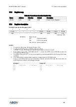
I2CDR (I2C Data Register): DFH
7
6
5
4
3
2
1
0
ICD7
ICD6
ICD5
ICD4
ICD3
ICD2
ICD1
ICD0
R/W
R/W
R/W
R/W
R/W
R/W
R/W
R/W
Initial value: FFH
ICD[7:0]
When I2C is configured as a transmitter, load this register with data to
be transmitted. When I2C is a receiver, the received data is stored into
this register.