


MC97F6108A User’s manual
17. Power down operation
189
17.5
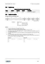
Register map
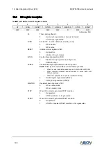
Table 26. Power Down Operation Register Map
Name
Address
Direction
Default
Description
PCON
87H
R/W
00H
Power Control Register
17.6
Register description
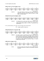
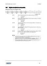
PCON (Power Control Register): 87H
7
6
5
4
3
2
1
0
PCON7
–
–
–
PCON3
PCON2
PCON1
PCON0
R/W
–
–
–
R/W
R/W
R/W
R/W
Initial value: 00H
PCON[7:0]
Power Control
01H
IDLE mode enable
03H
STOP mode enable
Other Values Normal operation
NOTES
:
1.
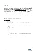
To enter into IDLE mode, PCON must be set to ‘01H’.
2.
To enter into STOP1,2
mode, PCON must be set to ‘03H’.
(In STOP1,2 mode, PCON register is cleared automatically by interrupt or reset)
3.
When PCON is
set to ‘03H’, if SCCR[7] is set to ‘1’, it enters the STOP1 mode. if SCCR[7] is cleared to
‘0’, it enters the STOP2 mode.
4.
The different thing in STOP 1,2 is only clock operation of internal 8kHz WDTRC OSC during STOP mode
operating.
5.
The PCON register is automatically cleared by a release signal in STOP/IDLE mode.
6.
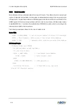
Three or more NOP instructions must immediately follow the instruction that make the device enter into
STOP/IDLE mode. Refer to the following examples.
Example 1
Example 2
MOV
PCON, #01H
; IDLE mode
NOP
NOP
NOP
.
.
.
MOV
PCON, #03H
; STOP mode
NOP
NOP
NOP
.
.
.