


20. Electrical characteristics
MC97F6108A User’s manual
232
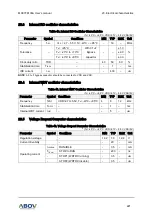
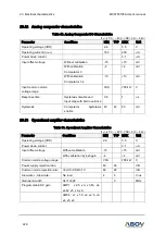
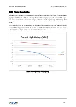
20.20
Operating voltage range
2.7
5.5
16.0MHz
(f
IRC
= 16MHz)
Supply voltage (V)
Figure 115. Operating Voltage Range
20.21
Recommended circuit and layout
{
}
MC
97
F
6
1
0
8
A
I/O
VSS
VDD
High-Current Part
Infrared LED,
FND(7-Segment),
,, ,,,
etc
{ }
0.01uF
VCC
0.1uF
This 0.1uF capacitor should be wit hin
1cm f rom t he VDD pin of MCU on the
PCB layout.
{
}
This 0.01uF capacitor is alternatively
for noise immunity.
+
0.1uF
VDD
VCC
{
}
The MCU power line (VDD and VSS)
should be s eparated from the high-
current part at a DC power node on
the PCB layout.
DC Power
Figure 116. Recommended Voltage Range