


MC97F6108A User’s manual
15. USART
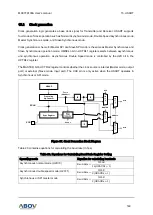
151
15.5
Data format
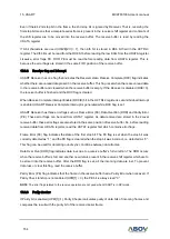
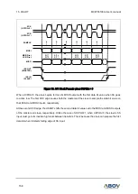
A serial frame is defined to consist of one character of data bits with synchronization bits (start and stop
bits), and optionally a parity bit for error checking.
USART2 supports all 30 combinations of the followings as a valid frame format.
1 start bit
5, 6, 7, 8 or 9 data bits
no, even or odd parity bit
1 or 2 stop bits
A frame starts with the start bit followed by the least significant data bit (LSB). The next data bits, up to
a total of nine, are succeeding, ending with the most significant bit (MSB). If enabled, the parity bit is
inserted after the data bits, before the stop bits. A high to low transition on data pin is considered as
start bit.
When a complete frame is transmitted, it can be directly followed by a new frame, or the communication
line can be set to an idle state. The idle means high state of data pin. The next figure shows the possible
combinations of the frame formats. Bits inside brackets are optional.
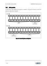
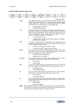
Figure 69. A Frame Format
Single data frame consists of the following bits
Idle: No communication on communication line (TxD/RxD)
St: Start bit (Low)
Dn: Data bits (0~8)
Parity bit ------------ Even parity, Odd parity, No parity
Stop bit(s) ---------- 1 bit or 2 bits
A frame format of the USART2 is set by configuring USIZE[2:0], UPM[1:0] and USBS bits in the UCTRL1
register. Transmitter and Receiver use the same settings.
[D7]
[D6]
[D5]
D4
D3
D2
D1
D0
[D8]
[P]
Idle
St
Sp1
[Sp2]
Idle / St
1 data frame
Character bits