


MC97F6108A User’s manual
15. USART
161
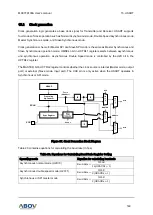
15.11
Register description
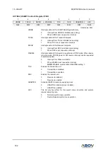
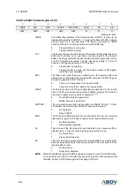
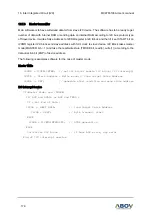
UCTRL1 (USART Control 1 Register) FAH
7
6
5
4
3
2
1
0
UMSEL1
UMSEL0
UPM1
UPM0
USIZE2
USIZE1
UDORD
USIZE0
UCPHA
UCPOL
R/W
R/W
R/W
R/W
R/W
R/W
R/W
R/W
Initial value: 00H
UMSEL[1:0]
Selects operation mode of USART
UMSEL1
UMSEL0
Operating Mode
0
0
Asynchronous Mode (Normal Uart)
0
1
Synchronous Mode (Synchronous Uart)
1
0
Reserved
1
1
SPI Mode
UPM[1:0]
Selects Parity Generation and Check methods
UPM1
UPM0
Parity mode
0
0
No Parity
0
1
Reserved
1
0
Even Parity
1
1
Odd Parity
USIZE[2:0]
When in asynchronous or synchronous mode of operation, selects the
length of data bits in frame.
USIZE2
USIZE1
USIZE0
Data length
0
0
0
5-bit
0
0
1
6-bit
0
1
0
7-bit
0
1
1
8-bit
1
0
0
Reserved
1
0
1
Reserved
1
1
0
Reserved
1
1
1
9-bit
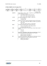
UDORD
This bit is in the same bit position with USIZE1. In SPI mode, when set to
one the, MSB of the data byte is transmitted first. When set to zero the
LSB of the data byte is transmitted first.
0
LSB First
1
MSB First
UCPOL
Selects polarity of XCK in synchronous or SPI mode
0
TXD change @Rising Edge, RXD change @Falling Edge
1
TXD change @ Falling Edge, RXD change @ Rising Edge
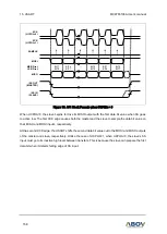
UCPHA
This bit is in the same bit position with USIZE0. In SPI mode, along with
UCPOL bit, selects one of two clock formats for different kinds of
synchronous serial peripherals. Leading edge means first XCK edge and
trailing edge means 2nd or last clock edge of XCK in one XCK pulse. And
Sample means detecting of incoming receive bit, Setup means preparing
transmit data.
UCPOL
UCPHA
Leading Edge
Trailing Edge
0
0
Sample (Rising)
Setup (Falling)
0
1
Setup (Rising)
Sample (Falling)
1
0
Sample (Falling)
Setup (Rising)
1
1
Setup (Falling)
Sample (Rising)