


Page 3–24
2101510 Rev. AG
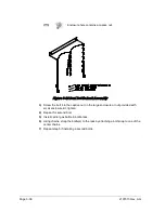
1)
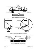
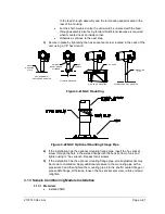
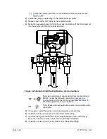
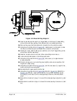
Locate the sample input fitting on the sample conditioning module (see
2)
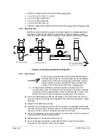
Locate the sample output fitting on the installed sample probe.
3)
Measure and cut the SST tubing to the required length.
4)
Make the necessary bends in the tubing to ease installation of the ferrule and nut
into the sample conditioning module input port.
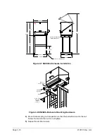
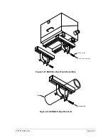
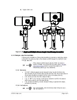
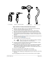
Figure 3-25 Sample Conditioning Module Line Connections
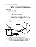
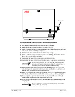
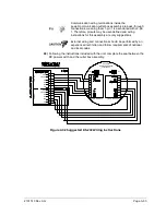
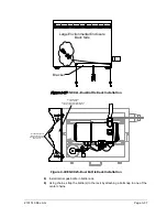
If sample conditioning module and NGC are located inside a
ENC82, review the following sub section,
to NGC inside of environmental enclosure, for
information pertaining to this installation.
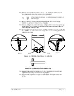
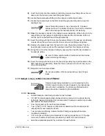
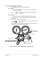
Tube, ferrule and nut should always enter the connection at a
right angle.
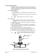
5)
If necessary, install the reducer into the sample probe output fitting.
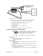
6)
Install the ferrule and nut onto one end of the sample tubing.
7)
Insert the tubing with the ferrule into the reducer/sample probe output fitting.
Move the nut down onto the ferrule, screw onto fitting and tighten.
8)
Install the ferrule and nut onto the other end of the sample tubing.
Содержание NGC8206
Страница 1: ...2101510 rev AG NGC8206 Chromatograph User s Manual ...
Страница 14: ...xii Figure 6 3 AC Charger Power Supply Wiring 6 28 Figure 6 4 Communication Troubleshooting Flowchart 6 30 ...
Страница 27: ...Page 2 8 2101510 Rev AG Figure 2 4 NGC8206 Enclosure Figure 2 5 NGC8206 Enclosure Left Side ...
Страница 60: ...2101510 Rev AG Page 2 41 hex socket set screw on cap Figure 2 32 Explosion Proof AC Power Supply ...


