


Page 3–32
2101510 Rev. AG
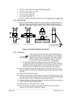
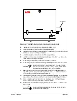
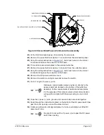
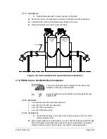
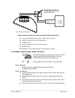
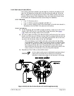
Figure 3-31 Power Wiring Diagram
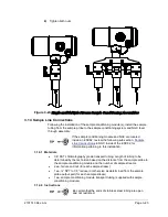
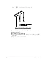
35)
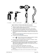
Feed the excess wire through the 6” nipple fitting, conduit seal, 5” nipple fitting
and out into outlet box opening. Pull sufficient wire to complete field wiring.
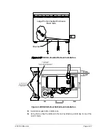
36)
Remove the power field termination J4 connector from the outlet box panel.
37)
Using the wiring instructions in
, install power (+) and power (-) wires
into the correct terminal pins and replace the connector on the board.
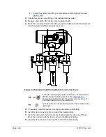
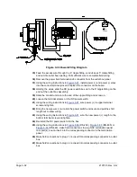
38)
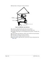
Holding the wires, slide the DC power switch box up to the 6” nipple fitting on the
end out the outlet box assembly.
39)
Slide the conduit union onto the end of the nipple fitting and screw on.
40)
Loosen the terminal screws on the DC power switch.
41)
Using the wiring instructions in
, wire power (+) to upper terminal
screw and tighten.
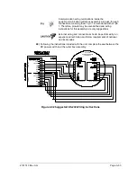
42)
Bring the new power (+) wire into the power switch enclosure and pull the short
length out to allow wiring.
43)
Using the wiring instructions in
, wire the new power (+) length to the
bottom terminal screw and tighten.
44)
Re-install the DC power switch into the box.
45)
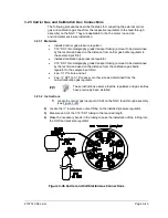
Using the wiring instructions in
(RS-485) or
(RS-422), make field connections to plug NGC termination panel
com port(s), and re-insert into the corresponding connector in the termination
panel.
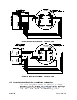
46)
Make field connections to plug J1, re-insert into corresponding connector in outlet
box.
47)
Make field connections to plug J2, re-insert into corresponding connector in outlet
box.
POWER
D1
J1
(-)
(+)
Содержание NGC8206
Страница 1: ...2101510 rev AG NGC8206 Chromatograph User s Manual ...
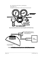
Страница 14: ...xii Figure 6 3 AC Charger Power Supply Wiring 6 28 Figure 6 4 Communication Troubleshooting Flowchart 6 30 ...
Страница 27: ...Page 2 8 2101510 Rev AG Figure 2 4 NGC8206 Enclosure Figure 2 5 NGC8206 Enclosure Left Side ...
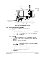
Страница 60: ...2101510 Rev AG Page 2 41 hex socket set screw on cap Figure 2 32 Explosion Proof AC Power Supply ...


