


2101510 Rev. AG
Page 3–49
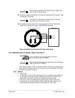
8)
Place the nut, front ferrule and back ferrule onto the opposite end of the tubing
and position so that the ferrules and nut screw onto the bottom of T assembly.
Screw nut until tight.
9)
Remove ferrules and nut from the thermostat end of the thermostat assembly.
Apply Teflon
®
tape to threads.
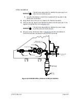
10)
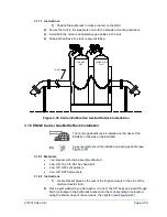
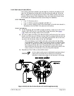
Insert tube end of thermostat assembly through the exterior wall on the side of
the enclosure (see
11)
Place the nut, front ferrule and back ferrule onto the end of the 3/8” bent tubing
inside of the enclosure. Position the thermostat assembly so that the nut and
ferrules screw onto the thermostat assembly.
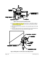
12)
Remove the ferrules and nut from end of the regulator assembly closest to the
service cock. Apply Teflon
®
tape to threads.
13)
Place the nut, front ferrule and back ferrule onto the end of the thermostat
assembly protruding from the enclosure.
14)
Hold the regulator assembly with the curved tubing up, above the protruding
tubing. Screw the ferrules and nut onto the nipple (see
15)
Apply Teflon
®
tape to the port one nipple on the filter/drain assembly.
16)
Insert the port one nipple on the filter/drain assembly into the output port on the
regulator and tighten the nut.
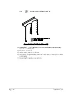
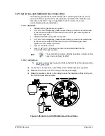
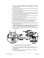
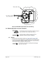
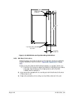
17)
Gently uncoil the temperature probe capillary tubing from the thermostat and
insert through the hole located below the thermostatic gas valve, being careful to
not crimp or make sharp bends in the capillary tubing (see
18)
Remove mounting screw and washers from the right rear NGC mounting bracket
(see
).
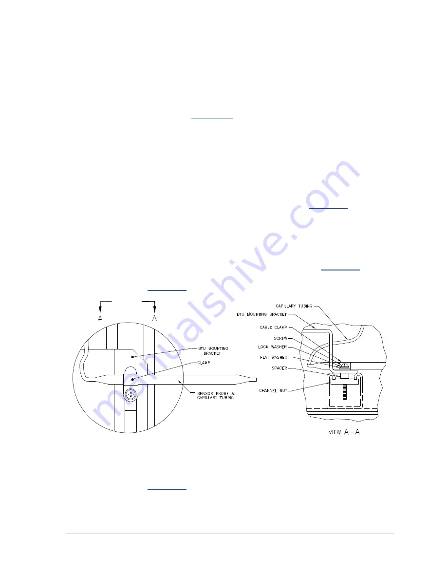
Figure 3-51 Temperature Probe Installation
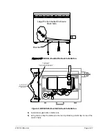
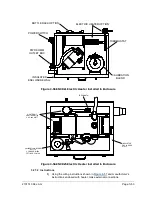
19)
Insert the screw with washers still in place through the hole located on the
mounting clip and re-insert through the mounting bracket into the channel nut
(see
20)
Position the probe underneath the mounting clip. Tighten the screw into the
channel nut to hold the probe in place.
Содержание NGC8206
Страница 1: ...2101510 rev AG NGC8206 Chromatograph User s Manual ...
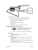
Страница 14: ...xii Figure 6 3 AC Charger Power Supply Wiring 6 28 Figure 6 4 Communication Troubleshooting Flowchart 6 30 ...
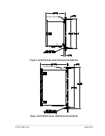
Страница 27: ...Page 2 8 2101510 Rev AG Figure 2 4 NGC8206 Enclosure Figure 2 5 NGC8206 Enclosure Left Side ...
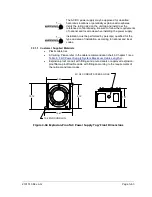
Страница 60: ...2101510 Rev AG Page 2 41 hex socket set screw on cap Figure 2 32 Explosion Proof AC Power Supply ...


